Unitron Notes & Interesting Articles Index

Unitron Model 132 4 inch (102mm) Equatorial Refractor Telescope
“among that class of the larger ’telescope-looking telescopes’ that many of us thought we’d never realize”
-
A discontinued product, posted for information purposes by Company Seven and with a historical perspective about the company who made it.
The Unitron illustrations here are from literature and of the telescope in Company Seven’s museum collection.
 Preface:
In August 2014 Company Seven acquired the Unitron 4 inch achromatic refracting telescope that is now exhibited at our showroom and featured in this article. The instrument was acquired from Xavier Debeerst, a collector and amateur astronomer in Belgium who owns the Arcturus Observatory and Anamorfose Curiosa, specializing in fine photographic art and collectables. He has much first-hand experience with these telescopes having amassed a collection of them, most just as they were distributed in parts of Europe under the trade names Unitron, Polarex, or Weltblick. Fluent in several languages and well traveled, Mr. Debeerst provided not only much of the hardware we describe here but he also helped us to better understand how they were distributed in Europe. The set was packed professionally, then sent by Federal Express Priority Air to Company Seven. This is among several used or consigned Unitron telescopes that have crossed our threshold over recent decades, but this is only the third, and so far the most imposing, of the Unitron telescopes to be selected for permanent retirement to our exhibit joining our Unitron Model 114 2.4 inch (60mm) Alt-Azimuth and Unitron Model 142 3 inch (75mm) equatorial telescopes. In July 2015 we added a
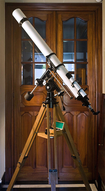
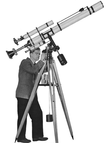
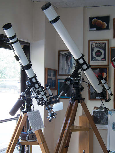
Right: Unitron Model 132 4 inch Equatorial Refractor telescope acquired in 2014 for permanent static display at Company Seven (128,015 bytes).
Exhibited alongside our Unitron Model 142/145 3 inch (75mm) telescope for comparison. Note the ceiling here is 9-½ feet (2.9 meters) tall.
Click on image to see enlarged view (216,475 bytes).
These elegant telescopes came to epitomize all that was great about traditional achromatic refractors - and all their shortcomings too. But these remained the class of well made telescopes that many purists, those who could afford them, aspired to use and admire. These telescopes remained in production and with very few changes from 1951 through 1992, by then these optical dinosaurs had been displaced from the marketplace by the more recently developed superior and more versatile apochromatic refractor and alternative telescopes.
This article is substantially similar to that which we wrote describing the
Why? for decades Company Seven has been on a mission to promote science education through astronomy. We do this subtly by helping to develop and sustain regional astronomy clubs, by donating equipment and expertise to start new astronomy programs overseas for elementary and junior high school age children, and locally with our own observatory and showroom. We conserve and exhibit telescopes and other instruments that have been worthy of note for attracting youth to astronomy, particularly since the beginning of the Space Age. Company Seven had been keen to acquire some Unitron telescopes for our display since these are among those landmark production telescopes that gave thousands of people their introduction to visual astronomy.
Our Unitron Model 114 2.4 inch telescope on the simple Alt-azimuth mount represents the pinnacle of that class of small refracting telescopes. It was among the best that a beginning amateur throughout the 1950’s and into the 1960’s might have aspired to own. Our larger Unitron Model 142/145 3 inch photo-equatorial telescope represents the most practical and versatile of the Unitron portable equatorial telescopes. This is as much at home outdoors under the night sky and yet is not overwhelming if left assembled on static display in a home. But it is our
The larger telescopes were ill suited for transport and did not fit (set up) in a typical room owing to their exceeding the height of most home ceilings, and so these were more likely to be dedicated to permanent installations at an observatory. At Company Seven our ceilings can accommodate much larger telescopes, so we display or store several Carl Zeiss and other refractors, we also show modern state of the art apochromatic refractors up to the Astro-Physics 206mm (8.15 inch) for comparison.
- Manual geared controls facilitate tracking celestial objects by turning only one control rod as, owing to the rotation of the Earth, the objects appear to move across the night sky. This is less distracting than operating an Alt-Az mount that must be continuously moved in two directions (altitude and azimuth) to keep on a celestial object of study. The tracking gear of the German Mount can be motorized, this automation permits the continuous tracking of celestial objects with precision good enough to allow photography of the objects or other projects that require keeping the telescope optical tube precisely pointed onto the target over time.
When the telescope mount is motorized and tracking a celestial object, then the user can conveniently refer back and forth from the eyepiece over to star charts or guide books and without the distraction of having to maintain a telescope centered on the object of study (as would be the case with an Alt-Az mount). It is easier to share a telescope with others over an observing session, particularly when they are inexperienced with the operation of mount manual controls. It becomes effortless to share the telescope when the mount is motorized and tracking objects automatically.
- The capability to vary the payload on the mount over a greater span than the alt-azimuth mount by simply adjusting the quantity of and position of counter weight on the shaft that extends from the mount on the side opposite the payload.
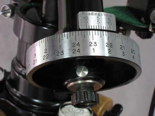
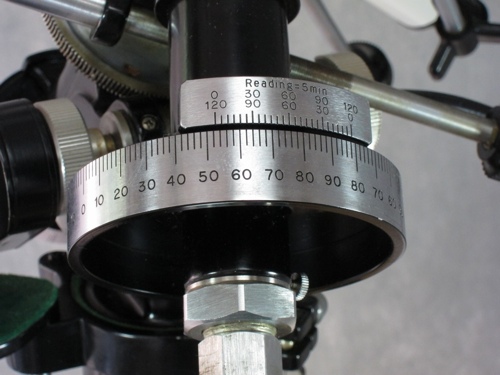
- Facilitates finding celestial objects in the telescope by means of the provided setting circle and vernier sets. These are an aid to celestial navigation whose moving numbered dials correspond to the two dimensional grid system, Declination and Right Ascension, that depicts the night sky.
- Cost of a new Unitron Model 114 - 2.4 inch telescope with simple Alt-Az mount = $125
- Average cost of rent per month was $80.
- The average cost of gasoline was 20 cents per gallon.
- Average cost of a new car was $1,700.
- The median family salary (wages before taxes) per week was $75.
- Cost of a new Unitron Model 142 - 3 inch Equatorial Refractor telescope = $435 ($3,881.60 in 2014 per CPIIC)
- Cost of a new Unitron Model 145 - 3 inch Photo-Equatorial Refractor telescope = $550 ($4,907.77 in 2014)
- Cost of a new Unitron Model 132/152 - 4 inch Equatorial Refractor telescope = $785 ($7,004.73 in 2014)
- Average cost of rent per month was $88.
- The average cost of gasoline was 22 cents per gallon.
- Average cost of a new car was $2,100.
- The median family salary (wages before taxes) per week was $85.60
- Easy Payment Plan: was a form of credit granted to customers who completed a simple credit application and were qualified by Unitron. These customers placed their order for a telescope accompanied with a minimum payment of 25 percent of the balance due. Optional accessories amounting to $50 or more could also be bundled into this payment plan. The customer received the telescope and accessories, then paid the balance due plus a 6 percent carrying charge over the next 12 month period. Customers who could pay the balance due in less than 12 months would receive a proportional refund of 4 percent of the original carrying charge. The first payment was due 30 days after the instrument was delivered, and if the customer sent payment for the remaining balance then no carrying charge would be applied at all.
As explained in the 1956 catalog “If your choice is the UNITRON Model 152, the 4” Equatorial priced at $785, the required down payment is only $196.25 with 12 monthly payments of $52.”
- Layaway Plan: the customer ordered the telescope but the order was held at Unitron. In the meantime the customer made payments (at least $10 each in the 1950’s) and when the total had been paid then the telescope would be sent to the customer. Aside from the cost of the equipment and shipping there was no additional interest, carrying charges or fees.
- 2 inch diameter eyepiece can show as much as 2.9x the area seen in a 1.25 inch eyepiece, or 5x the area of a 0.965 eyepiece
- 1.25 inch diameter eyepiece shows 1.7x the area of a 0.965 inch eyepiece
- 0.965 inch eyepieces can show almost two thirds the area that can be seen in 1.25, and one fifth the area that can be seen in 2 inch eyepieces
- 1951 United Trading Company, 204 Milk Street, Boston 9, Massachusetts
- 1952 UNITRON, United Scientific Company, 204-206 Milk Street, Boston 9, Massachusetts
- 1957 UNITRON Instrument Division of United Scientific Co., 204-206 Milk Street, Boston 9, Massachusetts
- 1960 UNITRON Instrument Company, Telescope Sales Division, 66 Needham Street, Newton Highlands, Massachusetts 02161
- 1965 UNITRON Scientific, Inc., 66 Needham Street, Newton Highlands, Massachusetts 02161
- 1970 UNITRON Instrument Company, Telescope Sales Division, 66 Needham Street, Newton Highlands, Massachusetts 02161
- 1975 UNITRON, 66 Needham Street, Newton Highlands, Massachusetts 02161
- 1981 UNITRON Instruments, Inc., 175 Express Street, Plainview, NY 11803 (then a subsidiary of Ehrenreich Photo Optical Industries, Inc.)
- 198? UNITRON Instruments, Inc., 101 Crossways Park, West Woodbury, NY 11797 (still a subsidiary of Ehrenreich Photo Optical Industries, Inc.)
- 1992 UNITRON Inc., 170 Wilbur Place, PO Box 469, Bohemia, NY 11716
Later production telescopes sold in the USA may be accompanied by literature indicating the seller was "Unitron Instrument Company - Microscope Sales Division". This lack of continuity could not have helped the viability of the telescope product line in the USA.
It will be fascinating to observe the planets, moon and brighter deep sky objects through these telescopes and be awed, just as our predecessors were.
These rightfully have earned our admiration and their place on exhibit for all to see at Company Seven.
 A Brief History and Marketing Primer: these telescopes and their accessories too were manufactured by Nihon Seiko Kenkyusho, Ltd. based in Tokyo, and by its subcontracted vendors in Japan. The company was established at least as far back as the the mid 1930’s, then furnishing fine achromatic refracting telescopes, based on the Carl Zeiss type E air-spaced doublet achromat lens design, of at least up to 125mm aperture under the POLAREX or SEIKO SCOPE trade names. By 1951 the company had emerged from the ashes of the war and offered their initial assortment of what was to become an extraordinarily well integrated and comprehensively accessorized line of telescopes and mounts.
Above Right: Nihon Seiko in Japanese Kanji script. The first two characters translate to Nihon meaning Japan, and the other Seiko for success (54,097 bytes).
In the Fall of 1951 the United Trading Company (hence UNITRON) based in Massachusetts commenced marketing the telescopes in the USA. For most other countries they were marketed under the trade marks POLAREX or POLAREX, though some distributors also marketed them as UNITRON. We explain more about marketing and trade names at our Unitron Notes & Interesting Articles Index page. Their refracting telescopes were initially geared for the amateur astronomer and school science class markets, though the larger telescopes in particular attracted customers in higher education too. The Nihon Seiko telescopes were actively marketed until the discontinuation of routine telescope production in 1992.
Nihon Seiko marketed most of their transportable telescopes in two basic configurations: either with an Alt-azimuth Mount and wood tripod suitable for terrestrial and visual astronomy use, or with a German Equatorial Mount with wood tripod or metal pier that is better suited for astronomy uses. In terms of optical performance, mechanical quality, and comparative comprehensiveness of the system, these were among the better production telescopes sold from the 1950’s to the early 1970’s. As Unitron and Polarex distributors prospered, their offerings grew from the initial smaller models including the 2.4 inch telescope up to 6 inch observatory telescopes sold from the mid 1950’s. The largest ever produced was the massive 9 inch (225mm or 8.8 inch) made for permanent observatory installation.
Unitron evolved to offer microscopes and other scientific instruments, some that shared accessories or parts of accessories made for use with the astronomical telescopes. These instruments provide good performance in their day, beautiful appearance - they looked good just standing there, and were versatile given their well integrated system of accessories. While our community was saddened by the demise of the telescopes production, the Unitron company in the USA continues to distribute microscopes and other equipment. There are other companies bearing the Unitron name, including one distributing hearing aids, but these are not related to the Unitron that sold telescopes.
Marketing, Configurations, and History of the 4 inch models
The 4 inch telescopes were first introduced in the USA in the Spring of 1953. These were marketed in the USA and most English-speaking countries as 4 inch because the diameter of the objective (front facing) lens is the primary property characterizing a telescope. Even though marketed as a 4 inch, their lens cells and focusers are usually engraved D102mm and it is by their metric measurement that they were marketed in several countries overseas.
The 4 inch telescopes were first made available in the Alt-Azimuth (up-down and left-right moving) mount configuration and with the De-Luxe Focuser that was designated Model 150. In the following month the Model 152 was introduced featuring the 4 inch diameter achromatic refractor telescope supported by the German Equatorial Mount (in Germany this termed a “parallaktische Montierung”), this supported by a transportable wood Field Tripod and this set priced at $785. The Model 152 announcement also mentioned a photo equatorial version selling for $890, this was basically the Model 152 but furnished with accessories to facilitate guided astrophotography. These telescopes and mounts sets are heavy and too awkward for most people to carry for any distance. So one would transport the major components in their wood cases, then assemble the telescope in the field. Alternatively one could employ a wheeled dolly to facilitate rolling the set in and out of a garage for example. It would not be unprecedented to see such a physically large telescope installed in an observatory setting. In the summer of 1954, Unitron USA announced they were developing a pier to support their German Equatorial Head, this instead of the field tripod. This photo-equatorial configuration would be provided with the similarly recently announced weight-driven mechanical clock drive and configured for a permanent observatory installations; this would be marketed as the Model 166.
Each of these telescopes were marketed as a packaged set including a standard complement of eyepieces and many other parts, certainly enough to keep the new owner unpacking and figuring-out what they are for some time.
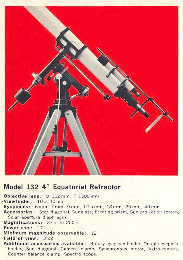 The 4 inch telescope we feature here was marketed in Japan and in several other countries under the factory’s trade name, SEIKO SCOPE, as the Model 132 - 4 inch Equatorial Refractor. In most other countries this telescope was marketed under either of the trade marks UNITRON or POLAREX.
Right: Unitron Model 132 - 4 inch Equatorial Refractor with Sun Projection Screen attached, as illustrated and described in a Seiko Scope catalog (81,896 bytes).
Click on image to see enlarged view (183,011 bytes).
The most notable attributes of the Model 132 telescope set are:
-
1. The optical tube is built around their 4 inch aperture (D102mm) 1,500mm focal length (f/15)* air-spaced doublet objective lens optical tube assembly. For comparison of what this brings to the observing session consider its smaller cousin, the 3 inch telescope that provides about 107 times the light gathering power of the unaided human eye; that is about 1.5x greater than that of the next smaller Unitron 2.4 inch telescope. The 4 inch provides about 1.8 times the light gathering power of the 3 inch telescope, and 2.8 times that of the 60mm; so even when observing the fainter deep sky objects within its reach the improvement in what is shown by the 4 inch compared with that in the next smaller telescopes are obvious. Of course with the larger aperture too there is a proportionate increase in resolution, the amount of details that can be seen under ideal conditions on the objects of study.
2. The Model 132 telescope is provided with a German Equatorial Mount and wood field tripod thus this is capable of tracking and expansion into astrophotography, and yet it remains a transportable telescope. The wood tripods provided with most 4 inch telescopes incorporate three wood legs that each consist of two straight long sections joined together. This late production telescope features articulated legs that can fold approximately in half for more compact stowage than the standard legs sold for most 4 inch models, similar to the arrangement of smaller Unitron telescopes.
3. The set was provided with an assortment of seven eyepieces, and with an Achromatic Amplifier (Barlow Lens), 10x 40mm Finderscope, Sunglass (thread-in solar filter) with aperture diaphragm, Sun Projection Screen. Three wood cases rounded out the set to accommodate the OTA, another for the Mount Head, and the third for the Field Tripod Legs.
The German Equatorial Mount provides:
The Model 132, or Model 152, or Model 4732 Telescope?
 Some readers acquainted with Unitron telescopes may be wondering why we refer to this telescope as a Model 132 or Model 4732, and not as a Model 152? This is because somebody in charge, probably at Nihon Seiko, failed to demand the standardization of model and part numbers among their world-wide distributors. So a telescope sold in Japan as the Model XXX was being marketed in the USA as something else (or not at all), or in Germany under yet another part or model designation. Frankly, even if Nihon Seiko had demanded standardization, then their own model numbering system would not have been our choice as it does not make as much sense as that of Unitron USA for example.
The Model 132 is at first glance identical to the Model 152, even down to the provided German mount and accessories. What distinguishes the Model 132 sold in several countries overseas from the Model 152 that was marketed in the USA and in some other countries too, is the difference of focusers. The Unitron 4 inch telescopes were first introduced in April 1953 provided on the Alt-Az mount, these were marketed overseas as the Model 134 or in the USA as the Model 150; these are similarly equipped and incorporate the De-Luxe Focuser. The earliest advertising image of May 1953 show the then newly announced 4” Equatorial Refractor telescope with the De-Luxe Focuser. Soon after this the telescope was marketed in the USA as the Model 152, and this included the larger diameter Super Focuser as standard equipment. Both focusers incorporate a manually operated locking clamp so that the user can secure the drawtube at any extended distance; this feature can prevent the weight of an attached payload from inadvertently shifting focus while observing or taking astrophotos.
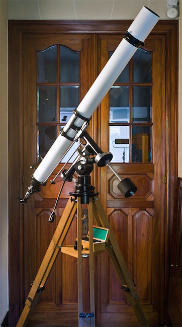
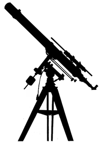
Left: A profile of perfect proportions! Our Nihon Seiko (Unitron) Model 132 - 4 inch Equatorial Refractor, note the standard De-Luxe model focuser (33,923 bytes).
Eventually the name became well enough recognized internationally that by the early 1970’s telescopes bearing UNITRON were being sold even in Japan. We know one person who purchased a new UNITRON 4 inch Equatorial Refractor in Japan in about 1973 and returned with it to the USA. For some forty years he thought that he owned a Model 152, but after reading this article he double-checked his original paperwork and realized his was in fact the version marketed overseas as the Model 132.
Just to add to your confusion, the example Model 132 4 inch Equatorial Refractor featured in this article was most likely sold new by the Unitron distributor in Germany. That distributor marketed this telescopes as their Model 4732.
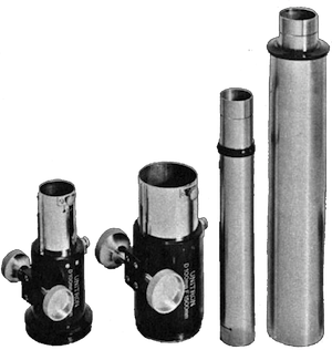 Focusers: the De-Luxe was the standard focuser provided not only on the Model 132 4 inch Equatorial telescope but also with the Model 134, the Nihon Seiko 4 inch Alt-Azimuth mounted telescope. While in the USA and in some other countries too these Alt-Azimuth telescopes were marketed as the Model 150 furnished with the Super Focuser, as were their USA equatorial mount versions. Either focuser is a rack and pinion arrangement that can accommodate the then common visual and photographic accessories that mate to either 0.965 inch or 1.25 inch diameter fittings, while the Super Focuser can accept those as well as the larger 2 inch diameter eyepieces and other visual and photographic attachments.
Right: Unitron trademarked De-Luxe Focuser at left alongside the larger Super Focuser, shown with their Drawtubes to the right (119,021 bytes).
Any of the 4 inch telescopes that would normally have been fitted with the De-Luxe Focuser could have been specially ordered, at some additional cost, with the optional Super Focuser. Either focuser could be purchased separately for the other smaller Unitron telescopes or by telescope-making amateurs for their own project, so a De-Luxe Focuser could have been upgraded later by the customer by ordering the Super Focuser. There are simple to change out since they thread-on and off of the telescope rear cell.
It would have been possible to acquire an Alt-azimuth mounted 4 inch telescope with the De-Luxe Focuser then adapt if for use with the German Mount, that would appear to have been a Model 132 sold overseas. It would have even been a simple matter to unscrew the Focuser assembly of the Model 132 and thread-on the Super Focuser, this would appear to be a Model 152 telescope. But it would have made no practical sense for a user to remove the Super Focuser provided with a 4 inch telescope and downsize that to the De-Luxe model.
Optical Tubes: the Unitron telescope optical tube assemblies are constructed from rolled and welded aluminum tubes, primed then painted gloss white on the exterior and antireflection flat black on the interior. In the case of the 4 inch models these incorporate a rolled tube of 4-3⁄8 inch outer diameter. The telescope optical tube accepts a spring-loaded lens cell at the front that is bolted on. Another metal cell, termed the Heavy Coupling in sales literature, is bolted onto at the rear of the optical tube. The heavy coupling provides added weight to help counterbalance the weight of the glass lenses and cell at the opposite end of the optical tube. The coupling is then equipped with either a thread-on Unitron De-Luxe Focuser or the larger Super Focuser.
With such a long focal ratio of f/15 these are lengthy telescopes, imparting more than their fair share of torque on a mount. Therefore, rigidity of the platform was a vital concern of the designers. When cased, then health and strength of the owner too are prerequisites to manage the nearly five foot (147 cm) long cased optical tube and the 51 lbs. (23.2 kg) weight of the cased mount head. Note, we at Company Seven consider these to be transportable telescopes and not pick up and go instruments.
The 4 inch Equatorial Telescopes Accessories: even by August 1954 there was a rapidly increasing assortment of goodies that one could add to their Unitron 4 inch equatorial telescopes. Some accessories under development then would never make it to market or would be renamed prior to being marketed; one product name most notably absent was the “super-secret UNIZOR” hinted at in their June 1955 advertising for example. By 1956 their catalog showed the telescopes and most of the accessories that would be the basis of the product line until its demise in 1992.
Nihon Seiko offered several basic versions of the 4 inch telescope with their German Mount. Some were marketed as the 4 inch Equatorial Refractor set up for visual work though these could be easily adapted to photograph the Moon, planets, and Sun. Other versions of the 4 inch telescope with their German Mount were furnished accessorized for astrophotography, these were marketed as the 4 inch Photo-Equatorial Refractor. Either 4 inch equatorial telescope was provided with at least the same basic accessories as our Model 132 including: auxiliary 10x 42mm Finderscope, a 0.965 inch diameter Star Diagonal (in some countries termed a Zenith Prism) 90-degree angled prism. The Star Diagonal makes it more comfortable for the observer to reach the eyepiece when the telescope is pointed to objects overhead. The image coming out of the rear of a refracting telescope would appear upside-down and backwards left to right, the Star Diagonal flips the image so that the object of study appears properly erect yet still backwards left to right; this is not as much a concern as comfort when observing planets or deep-sky objects. But Nihon Seiko ask includes a 0.965 inch diameter in-line observing image erecting Porro Prism that allows observing objects in their natural orientation too. These telescopes also included a cased assortment of seven or eight eyepieces, a Barlow doublet negative lens, a neutral density Moon Filter. Each telescope also included what Unitron termed the Sunglass, a light attenuating dark glass filter intended for use with the Aperture Stop though really not a safe filter for solar observing since it does not block infrared; this NOT recommended for use by Company Seven). The latter two filters slipped over the eyepiece and was held in place by tension of the thumbscrew. The eyepieces and filters were furnished in a fitted hinged-lid wood case, this set fit in a slot within the optical tube assembly wood case. Other accessories a battery-powered lamp that threaded into the base of the German Mount Head.
The equatorial models were also furnished with a Sun Projection Screen consisting of 1. perforated black anodized metal shade, and a 2. white-painted metal plate with both kept in-line by a 3. bracket-mounted support bar attached to the rear of the optical tube of the telescope, 4. Solar Diaphragm (Aperture Stop). The Aperture Stop restricts the opening at the front of the telescope and this prevents the full energy of the Sun, that would otherwise be focused by the objective lens into an intense beam, from heating and damaging the eyepiece. When employed with the aperture stop at the front of the telescope, the telescope projects an image of the Sun through an eyepiece attached to the the focuser, and onto the white plate. The perforated black shade casts a shadow on the white card except at the center onto where the Sun’s image is projected. This is a safe technique to observe sun spots or a solar eclipse.
The major components were shipped in wood storage cases, one for each of the major components and smaller cases for some of the accessories sets foo.
The Photo-Equatorial telescopes included other components to facilitate film astrophotography including: a 60mm (2.4 inch) x 700mm focal length photo guide telescope attached in parallel alongside the main 4 inch telescope. Since any 4 inch telescope configured for astrophotography was likely to accommodate heavier payloads, and since this was a more upscale model likely to be employing 2 inch eyepieces with a UNIHEX, then these were provided the upgrade Super Focuser and to help balance changing payloads at the rear of the main telescope a counterweight system is also provided, attached and parallel to the main telescope.
Those versions of the 4 inch telescopes that were initially marketed in the USA and in several countries overseas as the 4” Photo-Equatorial Refractor telescope were soon after designated the Model 155. Those sold in the USA and in some other countries as the Model 160 were similar but were equipped with the mechanical weight-driven clock drive. Those telescopes marketed overseas as the Model 132E 4 inch Photo-Equatorial included the Wood Field Tripod and were at a glance identical to the Model 160 sold in the USA as these were similarly equipped with the Super Focuser. But the Model 132E included the customer’s (or distributor’s) choice of either electronic Synchronous Motor or mechanical Clock Drive. The pier-mounted version of the set were marketed overseas as the Model 132F 4 inch Photo-Equatorial, while the pier-mounted version of the Model 160 was marketed in the USA and in some other countries too as the Model 166.
One cannot necessarily bank on knowing a used telescope was sold with this or that accessory since over time the original distributors may have scavenged or exchanged components, this was more likely to have occurred near the end of production at Nihon Seiko. Former owners too may have upgraded or changed out components. So a telescope originally sold as the Model 132 overseas might show up there or in the USA appearing as a fully accessorized Model 160 4 inch Photo-Equatorial Refractor years later. This is the case of our Unitron Model 142/145 telescope, that was originally purchased new then upgraded by the original owner over time to be equipped well beyond the Model 145 3 inch Photo-Equatorial Refractor.
Ours is among the later production examples featuring a fully multicoated air-spaced doublet objective lens labeled D102mm F1500mm (diameter and focal length), this was sourced from a well regarded maker in Japan. The telescope was acquired by Company Seven from a collector in Belgium, he had acquired this in Germany some years before. Since this is telescope has an original De-Luxe Focuser, and since the Unitron 4 inch equatorials sold in the USA (as the Model 152) incorporated the larger Super Focuser, and since elsewhere these were usually sold bearing the Polarex markings we suspect this Model 132 was originally sold through the Unitron distributor in Germany. The telescope was most likely sold no later than 1984, but not much earlier than that since the objective lens of older examples tend to incorporate violet-tinted magnesium fluoride antireflection coatings. In Germany these telescopes were marketed from the early 1960’s through the Spring of 1985 as UNITRON by Manfred Wachter Präzisionsmechanik und Optik of Bodelshausen at Tübingen (near Stuttgart), whose well illustrated literature remains a good source of information about these products even today.
This Unitron Model 132 telescope in our exhibit is unusually intact, and presents well. The 4 inch achromatic optical tube assembly shows few signs of having been used. The optics of this telescope and of all the mechanical components are original, intact, and functioning well. The greased components function acceptably well, but could nonetheless benefit from cleaning and regreasing before the telescope were put back into service. For static exhibit we find no need to disassemble the gears and bearings to perform that service.
The mount and tripod set has only modest signs of normal and careful use. The optical tube shows no signs of use or of aging. One small area of the Dew Shield does have some minor nicks on the that can be remedied with proper matching of the white paint. However, our priorities are to arrest decay and remedy where indicated, to replace missing or repair damaged components with original period parts, and to conserve for perpetuity. So we are rarely concerned about minor cosmetic issues. This telescope for example is missing the original Unitron Lens Cover that fits over the Lens Shade, so we will be on the lookout for that. In our efforts to restore the tripod for example we not only treated the wood to restore some of its former glory and preserve it better. We replaced one broken plastic knob capped wing nut, and another that was incorrect for this set. Fortunately there are many of these telescopes and their components in various states of repair for sale around the world, and so it is usually a matter of time and luck to find original replacement parts.
Upon first inspection of the 4 inch objective lens we observed there were some particles in the narrow air-space between the crown and flint lens elements. There was some spotting, a possible precursor of fungus, between the lenses (R2, R3) and on the rear element back surface (R4). The Newton Rings appeared decentered. To solve these issues required careful disassembly, professional cleaning and treatment, and reassembly. Throughout the process there must be a disciplined and proper technique; we will not explain how to do this work here because we do not recommend tampering with or disassembly of these lenses by those who are not trained in the work. Fortunately, we were able to restore both elements of the objective to an as-new appearance. After cleaning and reinstallation into the cell the lenses are clear. Our alignment process resulted in even better performance than when the telescopes were first evaluated at Company Seven, now showing the clearly defined and concentric Newton’s Rings interference pattern.
We have observed some advertised specifications for the objective lens these 4 inch telescopes call for a 102mm (4.02”) or even a larger 105mm aperture. Their lens cells and focusers are engraved D102mm or 105mm (4.13”) aperture objective. We measured the actual clear aperture of our Model 132 as 99.80mm (3.93”), that amounts to a 4.6 percent difference in light-gathering power yet we see nothing sinister about the discrepancy, it just offends our sensibilities - maybe our obsession with fact. In our decades of experience working with manufacturers and with distributors of telescopes, one not always being the other, we observed numerous instances where the people who write the marketing literature are not fully acquainted with the product. Because of this, some of the discrepancies between what is advertised and what is delivered originate simply from a misunderstanding. Or, the advertised specification may refer to an effort by the writer to simplify; 4 inch is easier to convey than 3.9 inch for example. If the clear aperture of the lens is 99.80mm while the overall diameter of the lens set unmounted from the cell is closer to 102mm (by our measure) then here too we can understand someone interpreting the focuser should be labeled 102mm and the marketing could reflect that too.
Some of the components bear stick-on labels that indicate they were made in Japan. Unfortunately there are rarely any serial production numbers on these telescopes optical tubes or mounts. While there may be a number related to production by a subcontractor on a lens set for example, we have not found any markings on the lens or cells of those Unitron telescopes in our exhibits to give any hint about their distributor or original market region, or date of production.
Regardless, if our particular telescope is not well documented then we can imply a production date range based on some of its features. So we may deduce or speculate about the issue of when it was made, even if we can not say for sure when it was sold. Even if some of the accessories or even the objective lens date to between about 1982 to late 1984, we must consider it is possible that accessory could have been previously interchanged with one from other telescopes, or replaced years after the telescope was originally sold.
Right: Unitron cased accessories including standard eyepieces and filters, and with the optional 4mm eyepiece for our Model 132 telescope (60,039>.
The fact that some eyepieces bear the name Unitron or Polarex or none at all is not unusual especially later in production because Nihon Seiko was scrambling to fill orders for distributors from dwindling production and a diminishing pool of inventory. Furthermore, it is not uncommon for owners to have lost or traded and later replaced or acquired eyepieces with whatever labeling or not became available.
The cased accessories set is complete, with all the pieces and parts mentioned earlier in this article. The eyepieces and filters are stored in their fitted hinged-lid wood accessory case, that fits in a storage slot within the optical tube assembly wood case. The wood case of the optical tube assembly has spaces to accommodate the provided Star Diagonal and Porro Prism. Furnishing a Porro Prism for such a long focal length telescope and for one sold on a German Mount strikes us an anachronism, unless someone observing the Moon might prefer the correct orientation. These are all shown in the photo at right, housed in the eyepiece case.
The mount head is furnished with a latitude adjustment mechanism, this allows fine adjustment of the tilt of the mount head when Pole Aligning. The range of latitude where the mount can be aligned, on a level surface, spans from 55 degrees down to about 42 degrees where only one thread remains securing the coupling. When nearing the operating limits of the lower latitudes then only one or two threads are supporting the load, and so it would be critical to lock the main bolt at either side of the mount head.
The wood Field Tripod is uncommon in that the legs can be folded into a more compact form for transport. There is some flaking of the black paint on the wood tripod metal leg tips, but this seems to be the norm as the tips of many Unitron tripods were not well primed before painting.
The hinged solid wood telescope and mount cases arrived in good condition, with no damage to the support braces inside as is often seen in other examples; this is a testament to both the packaging skills of Mr. Debeerst and the handling care of Federal Express. The cases needed only some cleaning and conditioning before being added to the exhibit. Since our general policy is to conserve antiques - to clean and protect them from decay, we display this telescope among our exhibits at our showroom cleaned and assembled but otherwise as it arrived.
Unitron Equatorial Refractor telescopes were sold new equipped with several eyepieces and choices of interesting accessories such as the UNIHEX or a Star Diagonal; ome of these accessories would be optional for telescopes sold overseas including our own Model 132. The UNIHEX as the term for the accessory permits the user to store as many as six eyepieces at the rear of the telescope, dialing in one eyepiece after another thus varying the magnification quickly at will. In other countries what was marketed in the USA as UNIHEX bore other names, in Germany for example this was the Okularrevolver. Of course the 4 inch telescopes could be outfitted with the UNIHEX, and because most 4 inch Unitron telescopes sold in the USA and some other countries too were equipped with the larger Super Focuser and could accept 2 inch eyepieces a larger version of the UNIXEX was marketed in some countries to accept up to one 2 inch eyepieces and five smaller eyepieces too. The DEUTRON is another interesting, accessory that allows one or two observers to simultaneously observe the same object through the telescope. For astrophotography there is are optional photo-guide telescopes, optical tube counterweight set, even the ASTRO-CAMERA 220 too. Many of these accessories were provided in their own fitted wood boxes. Some of the accessories that are exhibited on our Model 132 telescope are described here:
Mechanical Weight-Driven Or Electric Synchronous Clock Drives: as the Unitron telescopes entered the market in the early 1950’s, a drive system to automate tracking along the Right Ascension (R.A.) axis of the German Equatorial Mount was not provided as standard equipment but was optional. The drive motor and gear reduction set would couple to and automatically turn the Right Ascension Worm Gear of the 4 inch Equatorial Mount at the rate of one revolution every 484 seconds (8.0667 minutes) to maintain tracking at the Sidereal Rate. Incidentally, the rate for the smaller 3 inch Equatorial Mount motor was slightly slower, and that of the 2.4 inch Equatorial was notably slower and so motors could not be interchanged even though they shared the same 9mm diameter hex drive shaft.
The mechanical Clock Drive, a weight-driven system, was announced as under development in the Summer of 1954. The Clock Drive is so termed because the the drive movements of first tracking telescopes were based on a conventional 12 hour clock movement but made to rotate once every twenty-four hours or once every 23 hours and 56 minutes at the Sidereal Rate. The mechanical Clock Drive features a speed control so the user can vary the rate to compensate for temperature change effects of the mechanism, or to change the rate for Solar (slower) or Lunar (faster) studies. This is not as responsive or precise, especially as the mechanism ages and wears, as an electronic motor-driven system or the later frequency regulated (Quartz, etc.) systems. An overseas Model 132 telescope sold new with the Clock Drive was marketed as the Model 132F. In the USA the Model 152, also sold without motor, was marketed as the Model 155 with this mechanical Clock Drive. The weight-driven Clock Drive continued to be offered as an option, selling in the USA for $605.00 near the end of production in the mid to late 1980’s.
Right: views of the Polarex labeled Model 132M synchronous 220v 50 cycle AC motor for our German Mount. The motor is shown here on a flat side but that is upside down, when installed the Motor Tray attachment bolt is at the bottom. At center note the swiveling gearbox assembly atop the motor. At far right the interior showing the transformer and motor (97,057 bytes).
Most telescope Drive Correctors of the period permitted the user to make fine adjustments to the tracking speed by dialing to a Sidereal, or Solar and or Lunar rate. The more sophisticated Drive Correctors included a hand held controller that made it easy for the user to make momentary corrections of Right Ascension (and Declination if the telescope mount had that second axis drive) that might be necessitated by the worm gear error or by slight Pole Alignment errors. Lacking a drive corrector the Declination control movements would have been performed by finely turning the manual Declination Control flexible cable.
Left: a Model 132M synchronous motor attached to the R.A. Gear Coupling (note the thumbscrew). The views show the R.A. Main Gear, Motor and Gearbox, Motor Support Tray, and Motor Tray Ring (101,120 bytes).
Selecting the correct motor meant specifying the mount, so this would be a Model 131M for 3 inch telescope mounts or the Model 132M for 4 inch mounts*. The correct mains voltage and frequency/cycles in Hertz for the region, this would be labeled 100v 50
There are 12 volt DC to AC power inverters available that would permit operating the motor from a portable battery pack. However, it would be vital to insure the inverter provides the correct frequency. So for example, a simple 12 volt to 220 volt AC 60 cycle inverter would play havoc on the tracking rate of our Model 132M 220 volt 50 Hz motor. To learn more about how these motorized telescopes may have been operated and controlled in the field, study the Model 142 telescope in our exhibit that includes the Unitron 115 volt 60 cycle AC Synchronous Clock Drive and with a Gieseler Electronics AccuTrack Model 2117B Single Axis Drive Corrector, that provides square wave AC power to the Right Ascension motor. Gieseler Electronics, founded by Time Gieseler went on to sell third party telescopes too and in time branched out into the selling of imported telescopes bearing the Orion Telescopes brand.
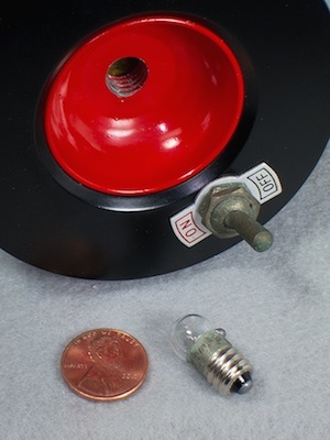
Right: Unitron telescope tripod shelf illuminator, front and with the rear open to show battery compartment (46,055 bytes).
This consists of a spring-loaded compartment holding two conventional flashlight batteries that threads onto a machined housing, the housing incorporates a flashlight light bulb with a red reflector this controlled by an on-off toggle switch. The miniature lamp is a common 2.5v 0.3A Edison E10 (10mm) base screw with CR2 filament: GE G11 or 14AC/DELCO. The assembly should thread into the bottom of the center casting that joins the three tripod legs to the 4 inch mount head. When switched on the lamp illuminates the accessory tray below.
Left: Unitron shelf illuminator bulb, shown alongside Lincoln Penny for comparison (41,443 bytes).
We underlined the word should because in theory the assembly threads into the base of the mount. We have observed many minor changes of dimensions and thread pitch over the forty years of production, and so finding a shelf illuminator is one thing but getting it to thread into your mount may be another matter. This brings up the issue of variations of specifications of production over the years. Our late production Model 132 mount has threads 60.0mm in diameter, while the threads of the illuminator measure 62.5mm and so these are incompatible. Nonetheless, the illuminator looks good in the photos here and on static display too.
This is a relatively obscure item that is rarely found in good condition today. We suspect this is because the then popular general purpose zinc-carbon dry cell batteries of that era were notorious for leaking (sooner or later) and corroding the device hence it was likely discarded. For this reason, those used illuminators that have survived likely did so because the user was in the habit of removing the batteries from the device when it was not being used for any extended period of time. By the 1970’s there were more handy compact flashlights coming onto the market, and so the need for this fixed accessory declined. Many of these portable lights provided the lamp could be filtered red to suit the users preference, and so these could do double duty for regular use around the house or filtered dim red for reading charts and guides alongside the telescope. Of course, the original owner may have been misplaced the item, or a new owner may not have understood the purpose of the illuminator or where the illuminator is to be installed. So, it appears that many of these were lost or discarded.
When employed in moist or high dew environments then over time the light bulb or socket, even the on-off toggle switch too could corrode and fail to illuminate so it it likely that a number of these simply fell into disrepair and were discarded. Fortunately for our exhibit, our Shelf Illuminator arrived apparently unused and in its original packing. Even still the visible metal parts of the Shelf Illuminator switch, the bulb screw thread, and the spring in the battery comport too signs of minor surface oxidation.
Right: UNICLAMP ring at left, and shown at right attached to our Model 132 4 inch refractor optical tube (83,575 bytes).
The UNICLAMP Camera Bracket should not be confused for the standard UNICLAMP. The UNICLAMP is a hinged ring designed solely to accept bolted on accessories, these were best sold by the pair to permit the fastening of accessories including Photo-Guide Telescope mounting rings for example
Stand by as we hope to add more and more optional goodies to our telescope set - and we will write about them too!
The telescopes marketed in the Americas under the trademark UNITRON were produced by Nihon Seiko Kenkyusho, Ltd. of Nozawa, Setagaya-ku, Tokyo, Japan. This company and its affiliates manufactured telescope and other scientific instruments. We have no substantial information about how Nihon Seiko Kenkyusho came to be, or when they developed their line of fine achromatic refracting telescopes. However, the company was established at least as far back as the the mid 1930’s, then furnishing fine achromatic telescopes of at least up to 125mm aperture to universities under the POLAREX and SEIKO SCOPE trademarks. By 1951 the company had emerged from the ashes of the war and offered an their first assortment of what was to become an extraordinarily well integrated and accessorized line of telescopes, mounts, and accessories.
Right: one of the first models offered by Unitron; a 2.4 inch Model 114 telescope of the Company Seven Museum Collection.
Japan had become the butt of 1950’s quality control jokes, “made in Japan” was generally not considered a compliment. But Japan’s industries improved, they became innovators, and the Japan of the late 1960’s into the 1980’s came to dominate the production of small moderate to excellent quality optics including telescopes, cameras and microscopes. Unitron appealed to the more demanding clientele, a limited portion of the marketplace. Nihon Seiko was not particularly innovative in that most of what they offered in the 1950’s had been developed and sold by other companied well before World War II. However, Nihon Seiko complied the most comprehensively accessorized lined of well-made telescopes if their day. Furthermore, Nihon Seiko allied itself with a series of exclusive overseas distributors who would actively promote the line so that by the late 1950’s almost everybody involved with astronomy in the USA for example had heard of Unitron, even if they could not afford one. Over the years Nihon Seiko were to stay loyal, one could argue unfortunately mired, to their offerings and principles.
The aspect of their history in the USA commenced when United Trading Company acquired the rights to distribute the Nihon Seiko telescopes and their accessories. United Trading was founded by Lawrence Fine with offices and a shop at 204 Milk Street, Boston 9, Massachusetts. Soon after going into business United became United Scientific Co. and developed an acronym under which the telescopes might be more readily recognized, the trade name UNITRON.
Simultaneously the telescopes continued to be marketed in western block nations of Europe and most Commonwealth nations (Australia, New Zealand, etc.) under the trade names UNITRON and or POLAREX. For example, in Japan and in some countries these sold under their trade name Seiko Scope; our 3 inch and 4 inch telescopes are among those listed in the Nihon Seiko catalog under the Seiko Scope Equatorial series. Some smaller quantity production lots of telescopes were made by Nihon Seiko Kenkyusho under other trade names including WELTBLICK (World View), but these are not anywhere near as common as those bearing UNITRON or POLAREX trade names.
Eventually the UNITRON became the most well-known of the trade names in no small measure owing to the proliferation of marketing advertisements in numerous astronomy publications by Unitron USA companies, and the prevalence of Americans visiting and residing for their work in many First World countries where there was interest in astronomy and the sciences and where these could be successfully marketed. The name became well enough recognized that by the early 1970’s telescopes bearing UNITRON were being sold even in Japan.
Given the limitations of the crown and flint glass available then, in order to provide good performance the better refractors made from the 19th through the mid 20th century are lengthy beasts. Typically their focal ratio, the ratio of lens diameter to their measure of basic image enlargement (or focal length), is on the order of f/15. Hence 4 inch aperture x 15 = 60 inches or about 1,520mm. So even our comparatively small Unitron Model 114, a 2.4 inch f/15 telescope, is challenging to work around with when housed within a six-foot diameter observatory dome as we exhibit it at Company Seven. Our 3 inch f/16 equatorial telescope stands so tall that it will just fit in a room of a typical home or apartment.
New accessories and minor adjustments continued as the telescope line got its legs in the marketplace. In May 1955 “UNIHEX” was announced as the name for Unitron's new six position rotary eyepiece holder; the competition to come up with the name was won by three amateur astronomers and each was awarded a UNIHEX. While each entrant in the competition was sent as a gift The Nature of the Universe, a book by Fred Hoyle published in 1950 that is based on his series of radio talks about astronomy presented on the BBC.
Adjustments to the line over the years included changes of designations and availability of some accessories. For example 2.4 inch models are usually referred to as 2.4 inch or occasionally as 60mm in the literature, but at least some of the telescopes of 1954-55 are engraved D 62mm F 900mm, by the mid 1950’s this would be changed and remain D 60mm F 900mm. Some earlier production telescopes may have no information about the telescope make or size on the lens front cell, only listing the basic UNITRON along with aperture and focal length on the focuser. In time the diameter, focal length, and UNITRON (or UNITRON) were painted onto the front cell in simple thin block lettering. But by the mid to late 1950’s the contemporary scheme of painting the front cell with this information, as is on our telescope, had become standard.
On our 1970’s production 3 inch telescope the provided objective lens covers slipped onto the front; these are embossed with UNITRON in lettering. The older telescopes might be a simple unmarked cover, or these could be a white painted cover with lettering in red (mid 1950’s). But in the late 1950’s Unitron settled into black with white painted lettering, this would be the norm through the late 1960s. Most were minor changes, but none that made one component or the other obsolete.
There was little in the way of true innovation with the telescopes or product evolution: the products available in 1972 were fundamentally the same as those shown in the 1956 catalog. At their inception Nihon Seiko accumulated wisdom from other accomplished makers then integrated these ideas into their production - and did so with class. What Nihon Seiko did manufacture was made after careful thought, with an above average degree of precision and uniformity, made of appropriate materials smartly engineered to work well and save weight. Each component was assembled by caring craftsmen who obviously took pride in their work. Nihon Seiko developed a well-integrated integrated system, for the time, and with a good selection of optional accessories. These accessories increased the versatility of the telescopes, while some of these items simply made it easier or more comfortable to use the telescope. These telescopes were produced in quantities large enough so that the economies of scale with then affordable Japanese labor allowed their prices to remain below that of the most highly regarded competing refractors (Zeiss, Goto, Tinsley, etc.). With numerous quality control steps throughout the process the factory insured every telescope made would be a garner admiration and confidence, as well as good performance for the new owner.
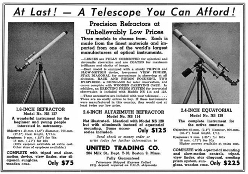
The first United advertisement in the Americas introduced their 1.6 and 2.4 inch aperture telescopes under the heading "At Last! - A Telescope You Can Afford!". This was submitted late in the Summer of 1951 for placement into the October issue of Sky and Telescope, soon after this was followed by ads in other issues and in Scientific American magazines too.
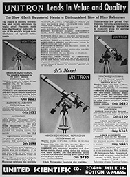
Right: April 1952 announcement in Sky and Telescope Unitron introducing the Model 142 (98,669 bytes).
A curious change between the two introductory advertisements and those subsequent ads that followed is that in the first two ads the Model 142 telescope is pointing to the right, while in following ads the same photo is reversed so that the telescope points to the left.
In time Unitron ads would appear in other publications too including Popular Mechanics and Science Digest too.
In 1952: the cost of this telescope set with two eyepieces and a standard diagonal (before the UNIHEX was available) was $125 plus shipping. This was a long time ago; President Harry S. Truman was still in office, the Korean War was still on. So to gain some understanding about the times and how the cost of this telescope compared to other typical expenses of 1952:
Interestingly enough, moreso for people of our times used to seeing prices escalate from year to year, the original selling prices of these telescope did not vary much between the 1950’s when they were introduced and 1970, yet consider the impact their costs would have had on a buyer. In 1952 the Model 114 telescope cost the average household nearly two weeks salary! If we refer to the U.S. Government Consumer Price Index Inflation Calculator (CPIIC) we see $125 in 1952 had about the same buying power as $1,115.40 in 2014, when this telescope arrived at Company Seven. Incidentally, the $585 of 1985 corresponds to $1,295.32 in 2014. So even their entry level telescopes were quite an investment for the average consumer.
Our Unitron Model 142 3 inch telescope we display is better accessorized than the basic Model 145 including accessories that were not sold in the mid 1950’s. The 4 inch Equatorial Refractor (Models 132 and 152) was announced in 1953.
In 1953 the Model 132 and Model 152 telescopes each cost the average household more than nine (9) weeks pre-tax salary!
Getting The Points Across: During the mid 1950’s the most noteworthy competitors of Unitron’s refracting telescopes were the Newtonian style reflecting telescopes and parts including those made by Cave Optical Company, Criterion Co., Edmund Scientific. So in 1955 Unitron unveiled a new part of its sales strategy that included humorous cartoons lampooning those bulky and heavier telescopes, and some competing refractors too. These are a few of those cartoons drawn for Unitron sales literature by the talented and acclaimed illustrator Ken Muse (b. 28 Apr. 1925, d. 19 Jun. 2010):
Above: cartoons drawn in 1955 for the Unitron catalog and other sales literature by illustrator Ken Muse (38,353 then 43,524 and 38,401 bytes).
The Model 166 4 inch, 5 inch and 6 inch pier-mounted photo-equatorial refractor telescopes had been in the product lineup since at least 1956; these had been the flagship models and appeared in catalog and in advertising media. By the late 1960’s plans were in the works to build even larger observatory based instruments, sold only on a special order basis, and the first of these was to be the 8 inch (200mm) model. Some of the advertising by Unitron USA in 1975 were among the last featuring the larger telescopes, Model 166 4 inch and 6 inch pier-mounted photo-equatorial refractors shown alongside each other, and with a woman standing alongside for comparison. However, we do not recall ever before seeing any similar advertisement or mentions in earlier Unitron or Polarex catalogs of their largest telescopes. Their largest model was developed in the late 1980’s and this was the 225mm (8.86 inch) f/14.7 refractor telescope also featuring a multi-coated lens, that would certainly have been a special ordered instrument.
Throughout production changes to the equipment were not arbitrarily made, and parts support remained excellent for some years beyond the formal demise of the telescopes distribution - this was good for those who choose to restore a Nihon Seiko telescope. It is not uncommon to find parts bearing various trade names on a used telescope since some years following the discontinuation of production their owners salvaged parts from various sources here and overseas. So for example one might find a POLAREX labeled 1980’s telescope with a 1950’s Seiko Scope labeled lens cover and with other parts labeled UNITRON.
Right: Objective Lens of our Unitron 4 inch Model 132 telescope. Note the aperture engraved reads 102mm. This lacks the red anti-tampering paint usually found on these cells (73,735 bytes). The same model lens may be found bearing the same basic lens specifications but with the Polarex trademark, these were for distributors outside the United States.
The two lens elements are kept apart at the nominal distance from one another by aluminum foil spacers. The three spacers are laid in at the edges and between the lenses, 120 degrees apart, and have no perceptible adverse impact on performance. The spacer is of the thickness determined by the lens design prescription, but when looking at a lens outside the cell then at first glance it is hard to see any air gap between the lenses. The lens elements and spacers are carefully slipped into a cylindrical lens cell and this is all held together by a retaining ring, the retaining ring is held in place by three bolts. The 4 inch and larger telescopes lens retaining rings features six adjustable push screws, these are adjusted to insure the cell is not threaded-on so tight that it compresses the objective lens. Such compression of a lens, or pinched optics, degrades the performance potential of the lens particularly when the lens and cell expand with temperature changes.
The entire lens cell slips onto the spring-loaded front cell of the optical tube, and is bolted into place and aligned (collimated) to the optical tube by means of the three surrounding flat head screws.
In photography too, in color or even in monochromatic (black and white) imaging sharpness is undermined, and bright stars will appear a bit bloated. This caused by the halo of secondary color that does not focus within the same area of the disc as does the red and green components.
Left: zoomed-in Digiscope of an Egret taken with a pocket camera. Before zooming in onto the Egret the image appeared well, but just lacking some snap. As the camera zoomed in then the image shows chromatism (violet false color) more and more obviously, especially pronounced where light and dark areas contrasts exist. The violet cast overall and the color fringing come from the lens of the pocket camera used to take the picture (124,684 bytes).
Regardless, chromatism was a common issue for most refracting telescopes and telephoto lenses manufactured into the 1970’s since the apochromatic refractive systems up to this time were costly and complicated to make - and even the best of the time could not equal what was to follow.
Above: Table above expresses optical properties including color correction in Nanometers at various Fraunhofer color lines (C to G).
For additional information about where the Fraunhofer lines correlate on the spectrum see below:
The Nihon Seiko lenses are so smoothly figured and polished to meet the nominal prescription that the final degree of spherical aberration of these Nihon Seiko achromatic lenses is quite good so visual images appear sharp and clear so any residual false color is not that problematic to the novice observer.
This is demonstrated when you look to the uncoated glass window pane of a door or of a display case for example, there is enough light reflected back at you so that you can recognize your own image and that of the surroundings. Furthermore, the cumulative effects of losses per surface can cause dramatic reductions in what can be observed of the fainter objects in particular.
AR Coatings Development: prior to 1935 all refractive lenses were made with no protective or anti-reflection treatments, the bare glass was exposed to the air or cemented to other lens components. The smoothly finished clean surface of a transparent material, glass or plastics, can reflect substantial incoming light. The light reflected depends on the properties of the material, the angle of the light source to that material (angle of incidence), and the angle of the observer to the surface, but this loss may be anywhere between four to about sixteen percent per surface. Consider what you see when you walk by a window pane? Your reflection. There is enough light reflected off that glass surface so that you can discern the image. The same thing was happening in telescopes, eyepieces, camera lenses - but worse. Since optical instruments and lenses consist of multiple elements of glass, there was the tendency not only to reflect light off the first lens surface but also to reflect light back and forth between uncoated air-spaced elements in the system. When multiple surfaces of glass are lined up, one behind the other such as in a telescope doublet or triplet lens or in an eyepiece, then these reflections tend to multiply as they reflect back and forth between each surface each slightly out of phase with the other to reduce contrast. This not only decreases contrast and overall light throughput, but reflections can cause a ghost’ or second image to appear. The observer would be likely to experience the effects of these issues when observing a star cluster for example where one or more faint stars may appear in the field where there would otherwise be none, or when observing a planet then the contrast and color saturation may be diminished. The result of treating a lens surface with an antireflection coating is to decrease flare and unwanted stray reflections, thereby reducing the potential of loss of contrast for an observed image.
Dr. Alexander Smakula (b. 9 Sep. 1900, d. 17 May 1983) led the team at the Carl Zeiss AG company at Jena that developed T-optic, the first anti-reflection coatings process devised for lenses. This was patented on 1 Nov. 1935 but kept a military secret throughout the following year. The first generations were a purplish tinted microns-thin layers of magnesium fluoride (MgF2) a metallic salt. When precisely applied in a vacuum chamber to the lens surface this reduces the amount of light reflecting off of a glass surface and thereby increases cumulative light throughput. These coating reduce undesirable reflections of light between glass elements thus increasing contrast and reducing the potential for ghost images. This was a noteworthy achievement in optics, and it kept Zeiss camera lenses and more sophisticated optics at the forefront of technology in the 1930’s. Initially only the more critical optics were treated, some of these are marked T for transparenz. Over time even optical lens components of devices intended for routine uses (eyeglasses, binoculars, etc.) were coated.
Antireflection Coatings Of Nihon Seiko: the pre-war Nihon Seiko amateur telescopes predate the development of the MgF2 coatings, so when looking into the lens one can see the whitish reflections clearly. During the course of production and spanning the the first thirty-five years or so after the war, Nihon Seiko specified every completed air spaced lens element was to be treated with Magnesium fluoride (MgF2) antireflection coating process, sometimes termed quarter-wave coating, to improve light throughput and to reduce the possibility of ghost images. The microns-thin single layer antireflection coating of magnesium fluoride coating presents with a purplish tint, this can be observed by careful inspection of telescope lenses as well as on their eyepieces too. Other components that incorporate refractive air spaced elements, including the finder, the glass prism inside the UNIHEX or DEUTRON and that in the Star Diagonal for example, will feature AR coatings. This is indicated in some of their advertising and in other factory literature by the mention of lenses fully coated. The objective lenses of the late production telescopes featured slightly improved multilayer antireflection coatings, usually presenting with a greenish tint. The long Dew Shield blocks out much of the stray light that can originate from the side (off-axis) of the objective lens, while the interior of the telescope optical tube and of each eyepiece barrel, and other in-line components are painted anti-reflection black.
The difference in transmission between the magnesium fluoride and the later multi-coating is not as significant as that between an uncoated and a single coated lens, though in more complicated lenses with many lenses in line (more complex eyepieces, etc.) then the benefits can be more apparent. The AR coatings subdue undesired reflections, otherwise it was possible to have one brighter star reflect back and forth between eyepiece elements thus giving the misleading appearance as though there were other stars in the field of view. The curves of these lenses are so subtle that ghosting could only rarely become a concern in practice.
The OTA Mechanical Aspects - This Is What A Refractor Should Look Like.
The optical tube assemblies of the Nihon Seiko telescopes, going back at least to the 1930’s, are fully constructed of rolled metal with cast focuser and front cells. The components have been painted in the traditional color schemes of black and white. Some very early examples with brass focusers for example may have left the factory in their natural finish. But the Nihon Seiko telescopes we usually see have a white painted optical tube with black painted front and rear cell, and focuser castings. The interior of the optical tube assembly from the inside of the slip-on Dew Shield, down the length of the baffled interior and focuser along with the provided extension tubes were painted with a flat black paint. This interior treatment contributes to the high contrast of these systems, systems where the background of space might appear as black as the blackest velour. The black dust cap (lens cover) slips onto the open Dew Shield, and this bears the UNITRON trademark in white on older models or has UNITRON molded into the front on later production models. Our 3 inch telescope and its 2.4 inch photo guide telescope covers have the embossed UNITRON.
The long focal ratio and precision machining of the optical tube and lens cell make it a fairly simple matter to assemble the mechanical components, install the lens, and have it be suitably collimated at the factory. Thus the smaller 60mm telescopes have no push pull lens cell or other means to adjust the lens alignment to the tube. The larger telescopes including our 3 and 4 inch models do feature a collimate able lens cell; this is also desirable because it facilitates removal of the objective lens for cleaning or transport and for precise installation.
The optical tubes of the early production small telescopes were bolted directly onto the mount saddle; this can be seen in the advertisement from 1952 shown above. These early production telescopes can be distinguished from later production (about 1955 and later) where the telescopes are attached onto the mount by means of detachable hinged mounting collar. Having mounting rings or a collar allows the user to loosen the collar enough to slide the OTA back and forth to compensate for changes of payload, this balances the instrument on the mount and results in smoother movement and less risk of damage if a clutch is accidentally loosened. The Unitron Model 142 in our collection employs the mounting collar.
Nihon Seiko sold telescope components to third parties too. One of the better known examples are the pale blue painted optical tube assemblies (OTA) sold by Don Yeier’s Brandon Company in the mid 1980’s. These 5 inch Brandon telescopes incorporate an f/8 standard Christen Triplet Apochromat objective lens (yes made by Astro-Physics Co.) mated to a shortened Nihon Seiko 5 inch telescope optical tube with the 2 inch focuser.
The Focuser: the De-Luxe Focuser was provided as standard equipment on the Model 132, or this could be purchased separately as an upgrade for other smaller Unitron telescopes or by telescope-making amateurs for their project.
The De-Luxe Focuser is built upon a body made of cast aluminum and with a diagonal-cut rack and pinion drawtube arrangement that is smooth when clean and provides 24.15mm of travel. Because of the limited focus travel the set included an 36.2mm (1.4 inch) diameter focusing sleeve, this is an extension section to be pulled out of the drawtube as needed. At the tip of the focusing sleeve is a friction sleeve into which 0.965 inch diameter eyepiece could be inserted. The friction sleeve could be replaced with one to accept 1.25 inch sleeve. Or the entire drawtube was removed to accept the UNIHEX with its own provided drawtube. The focuser body is painted black, and tastefully engraved with the engraving inlaid with white paint.
But to reach focus could be tedious since the focuser drawtube alone could not provide enough extension to accommodate as broad a range of accessories as were offered for these telescopes. So one needed to loosen the clamp at the end of the focuser drawtube (without letting the clamp fall off), then insert the appropriate focusing sleeve, then slide the focusing sleeve in or out of the drawtube and lock it in place (after you find the clamp that fell off) so that the accessory could then be attached and drawn in or out to reach focus by turning the pinion hand knob.
On the earlier production smaller telescopes, including our 2.4 inch Unitron, there is no drawtube lock provided. There is no way to quickly adjust the tension on the drawtube or the amount of effort needed to turn the pinion control knob. Most of these telescopes sold for astronomy were shipped with the smallest model of the UNIHEX, and this accessory alone adds some 3/4 lbs. (334 g) of pull on the drawtube, adding the eyepieces adds somewhat more. So one needs to rely on having the focuser pinion tension set so that it does not allow the drawtube to slide back (drawing the image out of focus) when pulled upon by heavy loads. The De-Luxe focuser incorporates a provision for locking the focus at any setting; a must for astrophotography, particularly when used with a heavy camera attached. The lack of a drawtube lock can be a deal breaker for anyone seeking to buy a smaller Unitron for astrophotography, so look for a focuser that incorporate the focus lock. Interestingly too, many of the smaller optical tubes packaged as photoguide telescopes lack any drawtube locking mechanism.
The focus control knobs of these telescopes were originally precision machined out of aluminum alloy, then anodized into a natural metal finish. However, between 1959 and 1961 Nihon Seiko transitioned their telescopes models over to attractive yet still durable black plastic knobs.
In the 1950’s it became common to hear the term “Made In Japan” being associated in a derogatory way with products exported from Japan since many items originating from there early after the war were poorly made or inconsistent. In an effort to promote and improve Japanese made products for export the government established trade groups to police manufacturers of goods for export; those manufacturers who complied with the quality and consistency requirements of the association could have their products bear an approval certificate or sticker. There were optical police too, so the better telescope manufacturers of Japan were affiliated with the Telescope Inspection Institute, hence the focuser of most telescopes made from the 1960’s into the early 1980’s may bear a sticker reading either “JTII̶a; or “Passed, Japan Telescope Inspection Institute”. The latter is the sticker affixed to the original focuser of our telescope too.
Above Right: De-Luxe Focuser, ordered by the original owner and installed by him onto our Model 142 telescope, shown with drawtube extended and with the extension installed.
One final observation; when a customer ordered an upgrade focuser from Unitron then it was not always guaranteed that the focuser body would have the telescope information engraved. The original owner of this Model 142 ordered the upgrade focuser and received one with no telescope OTA information, hence unlike the original focuser shown above right that is labeled "D 75mm F 1200mm", while the De-Luxe focuser is only engraved with the UNITRON name.
Finder Telescope: most telescopes that are if a comparatively high magnification design are furnished with a smaller, wide field of view auxiliary telescope that is often termed a finder because it helps the operator to find the objects of study and center them in the main telescope. These 4 inch refractors were originally furnished with one 10x 42mm aperture finder telescope, we measured ours as 10x 40mm. This is built on an air-spaced doublet lens, fully Mgfl antireflection coated, and with a 0.965 inch diameter crosshair reticle eyepiece; focus is adjusted by sliding the eyepiece in our out. The finder assembly is attached to the main telescope barrel by two brackets bolted onto the tube wall. With the 4 inch f/15 telescopes, even with their widest field of view 2 inch diameter eyepieces, not being able to see any more than about 1.5 degrees field of view (about three diameters of the Moon), the finder is an essential aid to point the main telescope onto the target quickly. If this telescope had been used more often then the original owner of this telescope might have come to realize, that particularly when operating with a German Equatorial style mount, it is helpful to have at least one additional Finder telescope attached along the area opposite of the original finder.
Each cast aluminum finder bracket has three support screws used to tip and tilt the finder so that it is aligned parallel to the line of sight of the main telescope. To focus the finder pointed the telescope onto an easy to find distant object, while looking through the finder eyepiece rotate the eyepiece to focus the dual line crosshairs. Finally, focus the finder onto the distant object by pushing in or pulling out the eyepiece and drawtube assembly to reach focus.
Right: Unitron Model 142 3 inch Mount Head Right Ascension axis main and worm gears set, roller bearings, shaft, and other components (49,348 bytes).
Competing systems then marketed to the consumer tended to incorporate less finely made gears sets, fewer precision bearings (if any at all), and their tripods tended to lack the rigidity of the products. While the Nihon Seiko mounts incorporated fine geared smooth controls, precise bearings, and clutches to allow precise manual control motions (up or down, left or right) of the mounts. One could set up the Nihon Seiko mount quickly, then track a planet across sky observing at high magnifications smoothly and with no jitter or point the telescope onto a distant ship and follow it across the horizon.
The equatorial telescopes were offered with a sturdy and attractive wood field tripod, these are fixed in their angle of leg spread. The tripod provided with the mounts made to support the telescopes of up to 3 inch were articulated, made to fold about in half for more compact stowage. The larger 4 and 5 inch telescopes were offered with the choice of either the fixed height wood field tripod or with a metal pier for permanent installations; these legs too were provided with wood storage cases and could rival a telescope case in length overall. Later in production the tripod made to support some of late production 4 inch telescopes was made to fold in half too, similar to the storage arrangement of the smaller 3 inch tripods. The folding legs on a 4 inch Equatorial set are uncommon, this is another interesting aspect of the Model 132 selected for exhibit at Company Seven. The 6 inch and larger telescopes mounts were offered only with the metal pier, there was no field tripod offered as they were not likely to be transported about.
For the customer who intended to use the telescope primarily for terrestrial applications and for casual visual astronomy then the altazimuth mount suffices. Furthermore, the altazimuth mount is simpler to set up and a less costly proposition. The altazimuth mounts were made available only with a matched portable wood field tripod. The wood tripod was intended to be folded quickly with the lower section rotating about the hinge at the middle of the leg, then rotating the lower section to store it neatly in between the upper leg spans. When extended the legs were supported in their proper disposition by means of a metal brace attached to the top of the lower section of each leg.
The mounts included with the Model 132 4 inch refractor and with our Model 142 3 inch refractor telescope set are a German Equatorial mount, each with a wood field tripod. Some of the mechanical details include the provided Setting Circles similarly provided with each mount, and the Clock Drive option. Shown below are details of our 3 inch model:
Above: Unitron Model 142 mount head details as exhibited at Company Seven; even after decades it inspires confidence and pride of ownership.
Both German Equatorial Mounts made for the 3 inch and for the 4 inch telescopes models incorporate Setting Circles with verniers. The Right Ascension setting circle that is engraved with the twenty-four hours subdivided with units in increments of ten minutes each, this can be read to an accuracy of one minute with the vernier. The Declination Setting Circle is graduated in degrees from 0 to 90 and engraved with 2 degree increments, this can be read to 5 minute accuracy with the vernier.
Assembly of the Mount and Telescope:
Extend the tripod leg extension sections, then attach the legs brace/accessory tray to keep the legs from accidentally spreading out under load. The tips of the tripod legs are of sharp and pointed steel, these will readily dig into the ground and stand fast. However, when setting up on very soft or wet ground Company Seven recommends placing a disc of plywood on the ground and under each leg tip to spread the load around a larger area. This will reduce the likelihood of the tripod settling in the ground, or even freezing into mud if the temperature drops through the observing session. For display indoors an optional caster pad under each tripod leg tip can protect your flooring.
We recommend setting up on level ground, alternatively you may put some block(s) under one or more legs to better level the set. Many owners employ a bubble level set onto or permanently affixed to the mount head, this to help judge when leveling. Next attach the mount head onto the tripod.
The Counterweight Shaft of the Unitron 132 mount head is a thirteen (13) inch long fully machined alloy bar, threaded ⅝ inch - 11 TPI (thread per inch) along its entire length. Of this about two inches threads into the female threaded socket of the mount head Declination Axis, leaving about nine inches extending from the mount to accommodate thread-on or later production slip-on counterweights. Thread the Counterweight Shaft onto the mount, then secure the shaft in place by tightening the sole ⅝ inch - 11 nut against the Declination Shaft housing threads, this is at the point where the shaft enters the mount socket. Then
Attach the telescope optical tube mounting collar onto the mount saddle (the topmost flat section of the mount), attaching this by means of two hand knobs. The telescope was set onto the collar and slid towards the front or back along the saddle until the optical tube reaches a nominal working balance point. Then swing the collar upper half down and over the telescope, secure the collar upper half to the lower half in place with the hand knob at the side of the collar.
The UNIBALANCE is a counter weight hardware set that were made to balance the telescope along its Declination Axis. The UNIBALANCE set consists of a 18-½ inch long x 0.35 inch (9 mm) diameter shaft with threaded ends that attach onto the tube brackets, this resembles those sets historically provided for many refractors including those made by Carl Zeiss Jena for example. The UNIBALANCE set is provided with one sliding 670 g. (1 lb. 7.7 oz.) counterweight that can be locked at any position along the length of the shaft, the shaft supported by a thread-in fitting mounted onto a 4 inch UNICLAMP Ring while the upper end of the shaft slides through a perforated fitting similarly attached to a UNICLAMP. Attach the UNIBALANCE set to the optical tube since this will facilitate changing accessories on the optical tube reducing the need to loosen the optical tube mounting collar to adjust the telescope position on the saddle.
Next loosen the clutches for Right Ascension and balance the telescope in that axis. Do the same for declination. To make fine adjustments in either axis first tighten the clutches, then turn the black hand knobs on either side of the rear of the mount head. The Right Ascension has a worm gear mechanism, so one can move the telescope throughout the RA axis with no interruptions, though care is taken to avoid binding the lengthy optical tube against the tripod. The Declination manual geared controls are spring loaded tangent style drives, and so the mount can only be moved so far by these controls without loosening the clutches to manually reposition the telescope, an unwinding the manual geared controls before resuming the tracking. When using the smaller Unitron Alt-Ax telescopes it was a simple matter while at the eyepiece to reach forward to turn these controls to track an object, but mounts such as this and for the 4 inch and larger telescopes incorporated flexible cables or steel rods to facilitate this.
Pole Aligning The Mount:
Proper operation of a German Mount requires the Right Ascension (R.A.) axis of rotation be aligned to be parallel to the axis of the Earth’s rotation. To achieve this at locations that you will frequent, Company Seven recommends you first level the tripod. By leveling when you first Pole Align the mount head you will not need to change the latitude setting of the mount again unless you travel north or south to other locations.
Loosen the azimuth (left to right, or longitudinal) adjustment clamp of the Nihon Seiko mount head assembly, this permits the user to smoothly rotate the assembly atop the field tripod and direct the mount head R.A. axis to point towards the Celestial North (or South) Pole. Then tighten this clamp. There is no fine adjustment mechanism to fine tune centering the mount in azimuth since the movement is smooth and can be refined easily enough.
Right: Model 142/145 German Mount of our exhibited Unitron 3 inch refractor, close up of the latitude adjustment mechanism (66,794 bytes). The installed set shown and circled in green to accommodate operation at latitudes of between approximately 26 to 40 degrees, the shorter mechanism shown removed at right is for higher latitudes of Approx. 50 degrees.
Adjusting the mount head tilt up or down when Pole Aligning involves first making certain the large stainless steel bolt that joins the Right Ascension axis housing to the mount head base post is adjusted just enough so that this joint may be articulated by hand but that this is not too loose either. When the mount head left the Nihon Seiko factory the nominal tensioning of this bolt would have been set. But if the mount had been used by someone doing astrophotography, or if used by someone not familiar with proper technique, then this bolt may have been tightened too tight to allow changing the latitude.
Left: Model 132 German Mount of our exhibited Unitron 4 inch refractor demonstrating latitude adjustment range as sold new for use in northern latitudes of Europe (84,622 bytes). On the Pole Axis is our Suunto Inclinometer to measure the range of latitude, this indicates a working range of about 42 to 54 degrees.
If you acquire a mount that is lacking the correct Nihon Seiko latitude adjustment components, a suitable replacement may be fabricated by a machinist with some guidance and using the original as a conceptual model. Alternatively one or two tripod legs can be shimmed with a wedge, a wood block can suffice, to allow the mount head to reach the optimum tilt in latitude - of course insure this is not so excessive a tilt that the set becomes unstable.
The latitude adjustment mechanism is not designed for use near the Equator, nor could the mount be aligned in Arctic regions owing to interference between the Right Ascension setting circle and the mount head post.
Finally, the Right Ascension Setting Circle is indexed either by pointing the telescope to a stars of and dialing in its coordinate, or by other techniques. The Declination Setting Circle need be set only once, it should not change orientation on its own but if this had been tampered with then this too can be set in several ways including the use of a level if the local latitude is known or it can be set by pointing the telescope to a known star.
Owing to the long length of the telescopes and fixed height of the tripod legs, people learned to work around the telescope standing when looking towards the horizon and possibly sitting on a low seat when observing objects overhead. This posed no major issues for most people and children when using telescopes of 3 inch and smaller. But by the time the design was scaled up to a 4 inch model, then when observing objects low in the distance shorter people would need to use a short step ladder to reach the eyepiece. But that is all part of the fun of having such a long optical tube to work around.
Eyepieces: a telescope is a light funnel that gathers light and forms one image; eyepieces are basically a magnifying lenses that are attached onto the focuser of a telescope to enlarge that image. The working magnification, numerous qualities of the image (field of view, clarity, degree of chromatism, etc.), and the comfort of the user while observing (eye relief) are determined not only by the qualities of the telescope but also of the eyepiece.
Right: One of the more interesting eyepieces ever distributed by Nihon Seiko in profile (20,747 bytes). From design in Company Seven’s Archives.
The UNITRON 1.6, 2.4, and 3 inch telescopes could accept interchangeable eyepieces of either 0.965 or 1.25 inch in diameter, although the standard four eyepieces provided with the set were 0.965. The 0.965 inch standard was referred to as the “Japanese” standard in some literature however, this standard was typical for telescopes made in the late 19th and early 20th centuries and predated Japan’s involvement in optics.
When originally introduced the 2.4 inch altazimuth telescopes were sold for $125 and furnished with a 9mm and 18mm 0.965 inch diameter eyepieces. The standard drawtube tip fitting would accommodate 0.965 accessories (diagonal, etc.). By 1956 most of the telescope sets, including the 3 inch model shown here, were provided with a set of four eyepieces as standard equipment: 9mm Achromatized Symmetrical, 12.5mm Kellner, 18mm Kellner, and 25mm Huygens. Telescopes equipped (as this one) with the UNIHEX or with a 1.25" diagonal would accept one optional 1.25 inch eyepiece. By 1963 Unitron included a new Achromatic Amplifier with the telescopes, this is a negative or Barlow lens that could be attached onto the barrel of the UNIHEX or the standard extension sleeve. When installed the Achromatic Amplifier increased the effective focal length of the telescope by a factor of about 2x, thus doubling the magnification of each eyepiece. The end of the eyepiece machined 0.965 and 1.25 inch diameter barrels are threaded to accept optional thread-on filters; though Unitron catalogs did not list any others than the Sun and Moon filters, many retailers sold color and other filters that complemented the telescope.
By the late 1980’s most new amateur telescopes, even introductory models, were built to accept at least 1.25 inch diameter eyepieces. Companies including Celestron that offered “Cometron” series telescopes with 0.965 targeted to the entry level consumer found the American customer and reviewers showed disdain for the old reliable standard in favor of the larger 1.25 inch eyepieces. The more advanced amateur and professional telescopes (not that too many professional astronomers ever look through a telescope anymore) incorporate focusers that can accept the even larger 2 inch diameter eyepieces. The attraction of the larger and larger eyepieces has to do with: 1. the potential for wider fields of view, and 2. improved eye relief.
In addition to magnification and quality of the image presented, the eyepiece determines the actual field of view; the area that can be seen. The field of view most accurately can be calculated when knowing diameter of the opening within the eyepiece barrel where the telescope image plane and eyepiece planes meet (Field Stop). Company Seven’s measurements of Unitron eyepieces show how the differences in maximum area that can be observed compare among the three popular eyepiece standards:
Optional eyepieces in the Unitron line from 1955 included: 0.965 - 4mm Orthoscopic, 0.965 - 5mm Orthoscopic, 0.965 - 6mm Orthoscopic, 0.965 - 7mm Achromatized Symmetrical, one 1.25 inch eyepiece the 40mm Kellner-Monochro*, and one 2 inch 60mm Kellner. While the provided focal lengths of the eyepieces never varied by much over the years the mix of models varied slightly, for example in most years the provided 25mm was a Kellner but later this was substituted for with a Ramsden. The offerings varied somewhat over the years but the choices for the larger telescopes in particular included 2 inch diameter eyepieces including their 60mm Kellner, the upscale 55mm Plossl and 32mm Erfle wide angle eyepieces. By 1985 the 2 inch offerings continued to show only one, the 60mm Kellner, being available. But by the mid 1980’s none of these eyepieces could compete for the attentions of dedicated observers against superior and more versatile eyepieces by competitors, most notably Brandon and Clave as well as the innovative TeleVue Optics.
Eyepieces Offered By Unitron Exhibited at Company Seven:
Nihon Seiko and the distributors Unitron and Polarex were successful at promoting the refracting telescope as the vision of what an astronomical telescope should be. The telescopes were not only providing amazing views and images of the night sky, but people were using them for terrestrial uses, and even for decorating a home or office. Their numerous ads appeared in periodicals including: Sky and Telescope, Review of Popular Astronomy, and Science Digest.
NASA’s Apollo 11 with astronauts Neil A. Armstrong, Michael Collins and Edwin E. Aldrin, Jr. aboard, lifted off from Kennedy Space Center’s Launch Complex 39A atop a Saturn V space vehicle at 9:32 AM EDT July 16, 1969 - the first Lunar landing mission. On July 20 their Lunar Landing Module descended onto the Moon touching down at 4:17:40 PM EDT (20:17:40 UTC). Many people around the world paused to share this televised moment live, and many more stayed up to watch Neil Armstrong step off the Lander and onto the Moon at 10:56 PM EDT (2:56 UTC) where he uttered “That’s one small step for [a] man, one giant leap for mankind”; never since then has the world been so similarly united (audio file is .mpeg format 83,968 bytes).
Left: Old Glory salutes the launch of Apollo 11 on July 16, 1969. The image size 5,840 bytes.
But other events were conspiring to distract America. The war in Vietnam cost so much in the way of lives, injury, and dollars that funding cuts for NASA loomed large. Budget and mission planning including the Mars Rocket, the hoped-for successor to the Saturn V, was stopped, etc. Administrators at NASA were wondering what next as the finality of the last Apollo mission planned for 1972 set in. Executive and Legislative leadership became ineffectual distracted by the Watergate scandal while the US economy was feeling pressure from high spending, trade deficits, rising interest rates and energy costs - and the consumer was starting to feel it too.
The Changing Marketplace
By 1970 it seemed as though any store that sold anything was offering some refracting telescopes, and these were nibbling away some of the market share for Unitron’s smaller telescopes. One could buy a reasonably well made refracting telescope of up to about 75mm (3 inch) aperture at Montgomery Wards, Sears and Roebuck that bore store brand trade names. One could buy Monolux, Tasco, Jason, Bushnell, Swift, from the increasing number of catalog and chain stores. These telescopes originated in Japan and many were surprisingly well made given their selling price with optical tube assemblies made of metals with glass optical components, often sold in their own wood carrying case too. By the 1980’s many of the lower priced telescopes transitioned to cheaper plastic components, some even with cheaply made plastic lenses, cardboard boxes were in and wood cases were history.
Competition from the many Japanese made achromatic refracting telescopes and from makers of other types of telescopes in the USA caused Unitron to gradually reduce their offerings. By 1970 the 1.6 inch Model 127 telescope was discontinued as few people were willing to spend $75 on a telescope this small no matter how well made. This left the 2.4 inch models as the smallest telescopes in the line. In 1970 the Model 114 sold for $125 in 1970, but by December 1972 the price increased dramatically, higher by about 1/3 to $165 for the set.
Some new domestic makers sprung up in Japan too, most notably Takahashi Seisakusho who in 1967 introduced their own TS65 2.6 inch refracting telescope with equatorial mount. Most of the Japanes telescope making companies that appealed to mass merchandisers competing on price disintegrated, leaving no dramatic impact on the market. However, Takahashi and another Japanese manufaturer Vixen Co., Ltd. would by 1977 jump on innovations that resulted from efforts by Nikon and Canon to improve their ultra-telephoto lenses. These companies, along with complacency at Nihon Seiko would ultimately destroy the f/15 maker’s competitiveness; more about this later too.
Other competing designs prospered too, among these were Newtonian reflecting telescopes most notably the Criterion RV-6, a 6 inch f/8 telescope selling for $194.95, and introduced in October 1970 was the Criterion RV-8 a $399.95 8 inch f/6 telescope. Cave Optical Company was doing a good job of making telescopes that competed for the affections of astronomers who might otherwise buy one of Unitron’s larger offerings. Edmund Scientific was moving from selling surplus components and optics to selling new telescope-making parts including mirrors and lenses, and complete telescopes. Of course Questar was still around, one of the few competitors still there since as far back as 1954, but their unique telescopes appealed to a clientele looking for something different than that which Unitron offered.
As images from space and the pace of life quickened through the later 1960’s it seemed there was less and less that could be left to the imagination. A glimpse of Saturn appearing with modest details no longer had the impact on a person coming of age then that it might have had for people who grew up in the 1950’s or earlier. By 1970 the American public had largely become used to space missions. When the Apollo 17 mission launched on December 7, 1972 this would be the last manned flight to the moon for that century as the originally planned following three missions had been cancelled as funding had been diverted. It is interesting commentary on the state of things when we recall many people telephoned their local television stations to complain when coverage of some Apollo missions interfered with routine programming!
New Competition: In 1977 Takahashi introduced the TS90, a 90mm (3.5 inch) f/11 Apochromatic refracting telescope. The TS90 was the first of a new breed of refracting telescopes* that were within grasp of the more demanding amateur. The doublet objective incorporates a crown element made of pure calcium fluorite, a synthetic grown under laboratory conditions. This design providing unprecedented clarity and freedom from false color (chromatism), and with a focal length nearly 2/3 that of a competing Unitron. This faster f ratio meant the Takahashi was more versatile, easier to transport, and its optical tube assembly could be mated to a lighter weight mount than that required to overcome the moment of the longer Unitron f/15 refractor. In 1981 Takahashi introduced their first 4 inch fluorite Apo, and at an even faster and more compact f/8 - with better performance and nearly half the physical length of a Unitron 4 inch f/15! By the early 1980’s Vixen too featured well made fluorite doublet apochromatic telescopes (lens similarly sourced from a Canon subsidiary), most notably the highly regarded Vixen 102FL. This 4 inch f/9 was distributed throughout the Americas by Celestron, this was a notable step in popularizing the Fluorite Apo refracting telescopes.
In spite of the changing marketplace Unitron continued to promote the company and astronomy. Jim Mullaney became the consulting staff astronomer for Unitron, helping to keep the product in the forefront while helping their customers progress in the hobby for about a decade. Few other companies of the time could provide before or after sale support like this. This was in part why some people considered Unitron to be the Aston Martin of telescopes.
Not yet appearing to realize how the market was changing, Nihon Seiko introduced new telescopes - yeeeup more ACHROMATIC refracting telescopes: an 8" (200mm) and 225mm (8.86) that were sold by special order. By the time these large refractors came about the product line, as elegant as it has been, was obsolete. Apochromatic refracting telescopes were taking over the traditional refractor market; these newcomers were being made in larger apertures and with much faster focal ratios too. The Apos could be made with physical lengths about half as long and lighter in weight than the Unitron. The compact Apos worked just fine on more compact mounts atop a shorter and more readily accessible tripod or pier. So any money saved by buying the achromat instead of a more costly apochromat OTA was cancelled out by the greater cost of taller stands and heavier mounts needed for the longer achromatic telescopes; this is before moving or housing a large f/15 telescope is factored in.
The shorter focal length Apo telescopes (f/6 and some even faster) provide superior color correction and greater versatility than the f/15 Achromats both for visual and for astrophotographic uses. Just consider an f/7.5 telescope can show four times the area of sky that may be seen through an f/15 system. The response to these technology developments from Nihon Seiko was....nothing really. Even if vendors Unitron and Polarex attempted to bring the changes happening in the market to the attention of management at Nihon Seiko, nothing came of it. Throughout the 1970’s and into the 1980’s there was no successful effort to develop Apo lens technology, or to source more versatile Apo lenses from third parties. So Nihon Seiko telescopes did not change, Nihon Seiko mounts did not change, the accessories did not change. Instead of working to protect the market they had developed Nihon Seiko elected to continue with what worked for them in the 1950’s. In retrospect it seems like Unitron was chopping away, but no chips were flying - they were basically stuck basically offering fine 30 year old technology.
Above: Unitron’s problem graphically represented: a Model 160 4 inch f/15 Photo-Equatorial telescope with provided mount and tripod (image 32,715 bytes).
Please do not get us wrong, we are not knocking these telescopes for fun. In their day these provided a good value and striking performance on the objects for which they were well suited. We are just trying to keep things in perspective here so that readers do not think they must run out and buy one of these classic dinosaurs without comprehending what they may be getting themselves into.
In an effort to compete better in terms of portability by 1980 Nihon Seiko introduced their folded refracting telescopes marketed in the USA as the Unitron Model 131-C (3 inch) and 132-C (4 inch). In this arrangement an objective lens is attached to the front of a short cylindrical tube assembly, the light from the objective is reflected by two tilted mirrors aligned within the optical tube so that the light cone exits the rear of the telescope. So the 3 inch optical tube for example now was only 19 inches long, about 1/3 the length of the conventional telescope, and 5 inches in diameter. The added complexity and cost of the two precision mirrors inside these folded telescopes however added cost (introduced at just under $700 for the Model 131-C 3 inch equatorial set) and weight to the otherwise simple refractor optical tube. By 1985 the 131-C set cost was $1,078 while the conventional 3 inch equatorial telescope Model 142 sold for $1,298, the difference attributable to the larger German mount provided with the Model 142.
What Company?: Changes of people and organization would be among the critical aspects to impact the company. The original United Trading Company and its descendants changed corporate identities and their locations of offices and distribution numerous times. In 1975 Lawrence Fine, the founder of United Trading Company, sold his interests in the company; he would die tragically two years later. By 1981 Unitron had been sold to Ehrenreich Photo Optical, a photographic equipment distributor. In 1982 Thomas A. Zappetti came to the company, he would control the helm of the Unitron companies through the end of telescope production to see it emerge as a well regarded distributor of microscopes and other instruments.
From 1975 on the Unitron companies distributing these telescopes appeared to change corporate identities as some people change shoes; this can be seen in the records of Corporations held by New York and other states where the respective entities operated. Consider how the company is represented in their literature at our archives:
The Demise
Nihon Seiko continued production even as Unitron was sold to a photographic equipment distributor in 1981. Unitron telescope sales group was no longer an independent entity, they had been relegated to something like a foster child as Unitron saw dollar signs by moving their attention to sales of microscopes and other equipment. Generally speaking the quality of the telescope and mounts was not cheapened over their years of production, though later in production some less obvious cost cutting was apparent to us. Consider their replacing the traditional leather strap provided for decades as case handles with a black flexible plastic strap. The smaller and cheaper latches on the cases of later production models. The UNITRON labels on their cases were originally made of painted high relief stamped metal nailed onto the case, later production models bear a simpler flat painted stick-on label.
In order to have something to sell that was comparable to the lower-priced imported telescopes being marketed through the 1980’s, Unitron ordered refracting telescopes of simpler construction. These telescopes were not made by Nihon Seiko, but were made by other vendors and are basically identical to the department store models being sold at the time, and were a far cry from the values that up to then could be expected of the Unitron name. At least some of these were made for Unitron by Towa Optics of Japan. Towa sold telescopes under their tradename and under other trademarks through retailers in the USA, their telescopes included the “Discoverer̶a; line sold by Sears Roebuck. One of these Towa telescopes is a 20 to 90x zoom 60mm achromat on a simple alt-az mount bearing the trade name "UNITRON" on the focuser, and with “UNITRON ED-U-SCOPE™” on the barrel of the telescope optical tube. Trying to cash in on the Comet Halley visit from 1984 to 1985, Unitron imported other less sophisticated telescopes some that made little sense for looking at Comet Halley. These included a 12 to 40x 40mm “Komet Spotter™”; this is among those many small telescopes being marketed then by people who knew nothing about observing comets to people who knew nothing about observing comets.
But the items offered in the product line seemed less competitive at the time in the eyes of management at Company Seven that we had no interest in offering the Unitron telescopes even as we rode the crest of Comet Halley visit from 1984 to 1985.
By 1985 the price of the Unitron Model 114 2.5 inch telescope had increased to $585, this was before the major effects of the devaluation hit. Company Seven observed the price of the highly regarded Japanese made products skyrocketed. The more demanding members our community did not suffer much from the loss of many items since more and more of the better products were coming from innovative US companies. However, the more economical to advanced range of refracting telescopes and equatorial mountings in particular became much more expensive commodities with few available substitutes for similar cost in the USA. This devaluation did have the impact desired initially, we slowed buying Japanese products. But the US companies did not bring back much production to the USA on the whole - they simply looked for countries where things could be made for less than Japan. It is interesting to note that Edmund Scientific then decided to bring the complete manufacturing and assembly of the Edmund Astroscan telescope back to the USA; the result was such a plunge in quality control that Company Seven discontinued selling the popular little telescope!
Just as Japan had been teased for its mimicking of foreign made innovations in the mid to late 1980’s, Taiwan and Korea then in the late 1980’s China made their entrance onto the world optics markets. The products that would displace Nikon Seiko other Japanese manufacturers on the low to middle range of the markets were coming from Korea, Thailand, China. These imports would for several years to come be among the shoddiest products sold to the uninformed US consumer.
By the late 1980’s the Chinese and Korean factories developed telescopes and mounts that so closely copied the external appearance (but not the performance) of competing products where the external resemblance is often so exact that only the paint can differentiate them. Vixen in particular suffered greatly as many of their products were copied in appearance if not performance. By 1988 the pace of manufacturing telescopes had appreciably slowed at Nihon Seiko as demand for Japanese made goods declined. Those who made the better, more sophisticated apochromatic refracting telescopes and accessories in Japan (Takahashi for example) prospered. Some Japanese companies began to shift their own production to overseas thus saving labor and real estate costs, and also avoiding having to deal with more stringent environmental laws taking effect in Japan. Nikon opened a plant in Thailand, Fujinon shifted some production to China; others would follow. The companies making the simpler achromatic refractors in other countries quickly took much of the available market share from Carton, Kenko Co., Ltd., of Vixen, other Japan-based factories and of course Nikon Seiko.
By 1990 Celestron who had been selling capable Vixen telescopes such as the 80mm Alt azimuth Refractor for about $550 was faced by Meade Instruments, their prime competitor, advertising a poorer quality 90mm achromatic telescope made in Korea selling for much than the Celestron (Vixen) 80. As a warning to our customers Company Seven mentioned in our web site "a very good 80mm telescope will outperform a lesser grade of 90mm telescope in many areas of astronomy". However, the typical consumer when poorly counseled and otherwise ignorant of details will usually choose that which appears to be the "best buy", and so the sales of imported Japanese made telescopes plummeted.
By 1992 Unitron was no longer in the telescope business, but continued to sell off remaining telescope and accessories inventory for years afterwards. By the late 1990’s a large facility was all that remained, with bits of this or that telescope here and there. By this time most US based manufacturers of good amateur telescopes who operated from the 1950’s through the 1970’s had gone out of business with the exceptions of Celestron International and Meade Instruments. And neither Celestron or Meade would survive as independent US manufacturing companies beyond 2007. Celestron was sold to a Chinese manufacturer, while Meade exported production to Mexico and China; artifacts of the unfortunate US administrations decisions - remember H. Ross Perot’s prediction about a Giant Sucking Sound?
There is one noteworthy U.S. company who have endured since 1954, and this is Questar Corporation of New Hope, PA. Known for making the Rolls-Royce of precision compact telescopes, they have endured since 1954 by not tampering much with what makes a Questar great - and by not having to answer to Wall Street.
The Internet continues to evolve and bring the world closer than ever, among the benefits are all the resources that helped one to not only find these telescopes used, or rare parts to make restore them, but also literature. Here are Unitron documents scanned by the host of this site that pertain to the 4 inch refractors featured in this article:
We invite you to visit our showroom near Washington, D.C. to see our exhibits first hand, or contact us by E-Mail to info@company7.com or telephone 301-953-2000. The showroom is open Monday to Friday 11 am to 6 pm, Saturday 11 am to 5 pm. We are closed on Sundays, on U.S. Holidays, and from 25 December through 1 January inclusive.
![]() Our 4 inch Equatorial Telescope:
Our 4 inch Equatorial Telescope:
accessories originally provided with the Model 132 and is exhibited at Company Seven with several of the then optional items too.
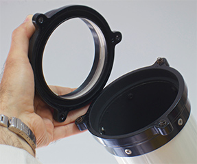
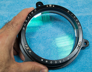
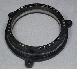
Center: telescope objective lens, after cleaning and illuminated to demonstrated the green multilayer antireflection coatings (82,557 bytes).
Right: telescope objective lens cleaned and ready to be installed onto the telescope, note lack of reflections (36,817 bytes).
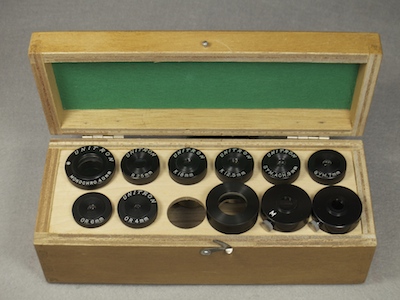 Included Pieces And Parts: the Model 132 set we show arrived equipped with numerous 0.965 inch diameter eyepieces, one 1.25 inch eyepiece, and other pieces and parts that were standard accessories. The Model 132 included: UNITRON OR. 6mm, SYM. 7mm, UNITRON SYM.ACH. 9mm, UNITRON K 12.5mm, UNITRON K 18mm, UNITRON R 25mm, UNITRON # 40mm MONOCHRO. (1-¼ inch). The # symbol of the late production 40mm eyepiece indicates this is the rarer and then more costly double-crossline reticle variant of the standard 40mm eyepiece. In addition to the provided standard seven eyepieces, our telescope arrived with the optional UNITRON 4mm OR eyepiece too. We explain these eyepieces and other optional eyepieces too in more detail later in this article.
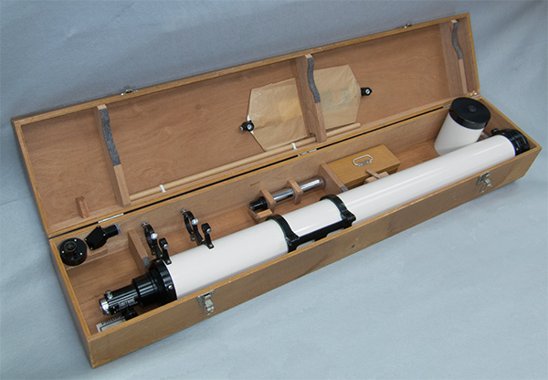
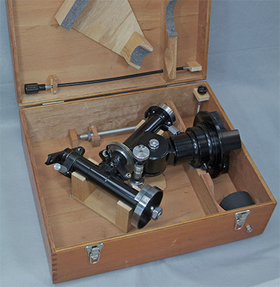
Above: our Unitron Model 132 4 inch telescope optical tube assembly and mount head as provided in their wood cases (99,350 and 78,006 bytes).
Prices Of The Unitron 4 inch Equatorial Telescope And Popular Accessories Over The Years
Item
Price In 1953-56
Price in 1972
Price in 1985
Model 132, 4 inch Equatorial Telescope
sold overseas, not in the USA
Model 152, 4 inch Photo-Equatorial Telescope set
Sold in USA, listed for comparison$785.00
$899.00
$2,350.00
Super Focuser upgrade
$15.50
18.50
10.00
UNIHEX A
$24.75
35.25
80.00
UNIHEX B
$24.75
35.25
80.00
DEUTRON A
$23.50
41.00
84.00
Second 10x 42 Finder (Incl. Mounting Rings)
$10.75
21.50
65.00
10x 40 Finder (Incl. Mounting Rings)
$18.00
33.75
90.00
Synchronous Motor Drive 115v or 220v, with hardware
$60.00
115.00
167.00
2.4 inch photo guide Telescope (Incl. Mounting Rings)
$81.00
123.00
230.00
Extra Counterweight to Balance photo guide Telescope
$4.75
9.80
15.00
ASTRO-CAMERA 220
$69.50
155.00
N/A
UNIBALANCE Tube Weight System
$15.50
26.00
57.00
4 inch UNICLAMP Piggyback Camera Bracket
$3.75
14.75
31.00
Sun Diagonal (Hershel Wedge), 0.965 inch Model A
$17.50**
29.00
63.00
Sun Diagonal (Hershel Wedge), 1.25 inch Model B
$22.50**
37.25
95.00
K60mm Kellner, 2 inch eyepiece
$14.75
35.00
38.00
Optional Accessories Of Our 4 inch Equatorial Telescope
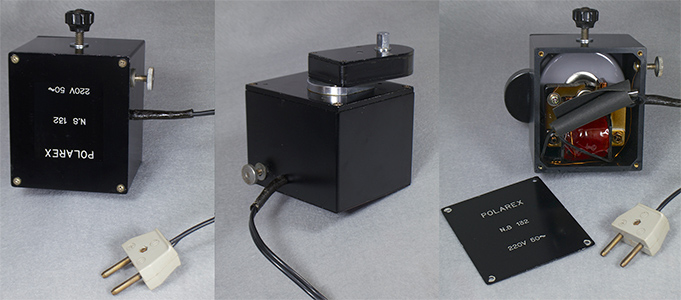 The more practical if less mesmerizing optional drive choice for these mounts is the Synchronous Clock Drive. This motor can be powered from either AC current or through an optional third party Drive Corrector that permits operation of the motor by either AC or 12 volt DC sources. The AC transformer within powers the synchronous motor, the motor turns a gearbox attached to the exterior of the casing; the gearbox can swivel about the axis of the drive shaft thus facilitating aligning the output shaft with the worm gear coupling.
Click on image to see enlarged view (250,356 bytes).
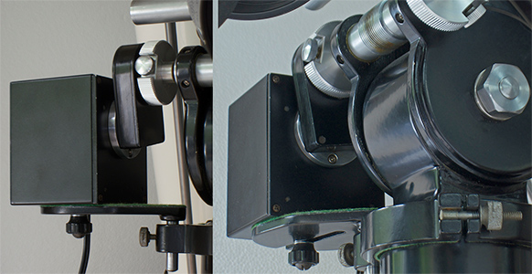 Installing these motors, at least doing so for the first time, seemed like some Rube Goldberg affair. Assembly requires attaching a clamping ring (a hinged split ring) to the Mount Head post; this ring resembles a conventional mounting ring but features a hole drilled through a dome protruding from one of the ring halves. The ring is rotated to either side of the mount until the ring hole is alongside the right ascension Main Gear Coupling, then the clamping rings are tightened. The motor support tray is attached by sliding its stainless steel post down from above and into the hole of the perforated Clamping Ring. The Motor Support Tray Bolt nut is loosened enough so that the motor can slide onto the slot of the motor support tray. The pivoting gearbox and the tray height are adjusted so that the 9mm hexagonal drive shaft of the motor and gearbox assembly align to the opening of the main R.A. Gear Coupling. Slide the motor shaft into the coupling, and manually snug the knurled round-head bolt onto the hex shaft to engage the motor. When the Motor Support Tray is at the desired elevation then tighten the Motor Support Tray Bolt nut. For times when you prefer to control the R.A. axis by means of the the flexible manual control cable then simply loosen the motor coupling bolt.
Click on image to see enlarged view (337,383 bytes).
![]() , 110v 60
, 110v 60![]() , or 220v 50
, or 220v 50![]() , etc. Since a synchronous motor can only rotate in one direction, it cannot be reversed, one would need to specify the direction of rotation either clockwise or counterclockwise; we have not seen any mark on a motor that would indicate whether it is for use in the North or South Hemisphere. The distributor would know to sell a motor with voltage, frequency, and rotation appropriate to their market area. If one traveled with their mount to the opposite hemisphere then the appropriate motor assembly would need to be provided, or with simple electronics skills the synchronous motor could be exchanged.
, etc. Since a synchronous motor can only rotate in one direction, it cannot be reversed, one would need to specify the direction of rotation either clockwise or counterclockwise; we have not seen any mark on a motor that would indicate whether it is for use in the North or South Hemisphere. The distributor would know to sell a motor with voltage, frequency, and rotation appropriate to their market area. If one traveled with their mount to the opposite hemisphere then the appropriate motor assembly would need to be provided, or with simple electronics skills the synchronous motor could be exchanged.
* The motor PN 132M is suited for routine applications with the Models 132/132E and with most other 4 inch equatorial refractors however, a heavier-duty motor was later made available for the Model 160 Photo-Equatorial telescope anticipating heavier loads and more rigorous duty. In the USA the standard motor was PN 16685 last selling new for $220.00, the heavier duty motor was PN 16686 that last sold for $312, about forty percent higher cost than the standard motor. Just to add to your confusion, the example Model 132 4 inch Equatorial Refractor featured in this article was most likely sold new by the Unitron distributor in Germany who sold their 220 volt 50 cycle motor to this telescope as their PN 471065.
With these products being marketed under several trade names it is not uncommon to find a POLAREX telescope with a UNITRON-labeled motor or vice versa as is the case with the set in our exhibit. Our motor is labeled POLAREX and N.S. 132 (N.S. is the maker’s mark for Nihon Seiko) with voltage and cycles; the information is engraved on the outward-facing cover plate. The earlier production cover is engraved with the tradename, motor model and voltage information while later production examples bear three or even four stick-on labels as does the motor of our 1975-era Unitron Model 142/145 3 inch photo-equatorial telescope. At first glance these may appear as one label since they are stacked one over another; one label will bear the tradename, another the model telescope, and the third will identify the electronic AC voltage and cycles, there may or may not be a Made In Japan sticker elsewhere on the motor housing.
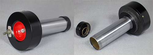 The Obscure Battery-operated Shelf Illuminator: in August 1954 Unitron in the USA announced their 4” Photo Equatorial telescope, also advertised as the Model 155. This advertisement also introduced their battery-operated shelf illuminator, and accessory for the wood tripod. The illuminator was advertised as late as at least 1972 as being among the additional accessories included with the Model 152 and with their Model 160 clock-driven version of the Model 155 telescope.
Click on image to see enlarged view (156,019 bytes).
Click on image to see enlarged view (110,366 bytes).
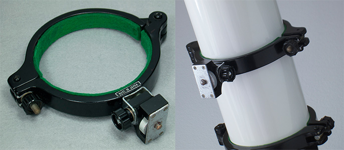 UNICLAMP Camera Bracket: is an option for our Model 132 telescope that allows one to attach a payload or accessory to the optical tube assembly, without drilling holes into the optical tube, by means of its ¼-20 tpi threaded attachment bolt. The most common use of the accessory was to support an optional camera, one suited for long-exposure “piggyback photography”. The UNICLAMP was included as an accessory with the astrophotographic-oriented 4 inch refractors such as the Model 155 and Model 160 and Model 166 telescopes marketed in the USA. We find the Model 155 to have been a bit anachronistic since it is basically a Model 152 telescope, similar to our Model 132 as explained above, but the Model 155 includes features that are needed only for astrophotography yet the set does not include any drive clock or synchronous. The Model 160 and Model 166 do include a drive set.
Click on image to see enlarged view (211,043 bytes).

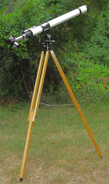
![]() Background:
Background:
This instrument has the UNIHEX A accessory attached holding the four provided eyepieces (309,461 bytes).
Click on images to see a striking enlarged view (1,014,604 bytes).
One amateur posted a comment that nicely puts these instruments into perspective in contemporary times:
The US distributor was then marketing as United Trading Co., before UNITRON became the registered trademark (116,544 bytes).
Click on image to see enlarged view ((192,267 bytes).
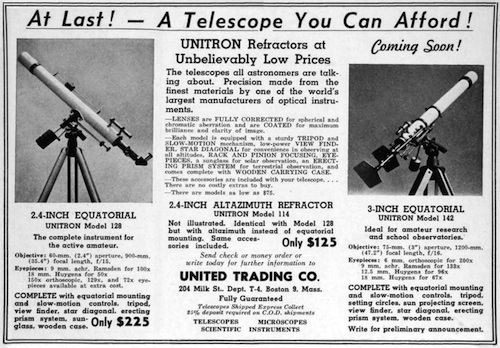 In the April 1952 issue of Sky and Telescope Unitron introduced the Model 142, 3 inch Photo-Equatorial model as "Coming Soon"; the same ad appeared in the May issue. This half-page advertisement did not announce any pricing information about the new telescope, but the ad invited inquiries from prospective customers. The June issue of Sky and Telescope carried the nearly identical half-page advertisement mentioning the price of the Model 142 as $435.
Click on image to see enlarged view (191,602 bytes).
 Enter Financing: By 1952 the first and only credit card in widespread use, Diners Card, had only about 40,000 card holders; this is a small percentage of the some 41 million families in the US at the time. So merchandisers offered other ways to help consumers buy their product. In 1954 Unitron instituted both their “Easy Payment Plan” and “Layaway Plan”. The offering of financing or layaway for products was not unprecedented even in the telescope market as other companies too offered similar plans at one time or another.
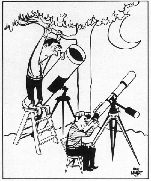
Mocking the inconvenience of
reaching the eyepiece of a Newtonian telescope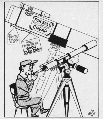
Giving up awkward and heavy for
comfortable and easier to use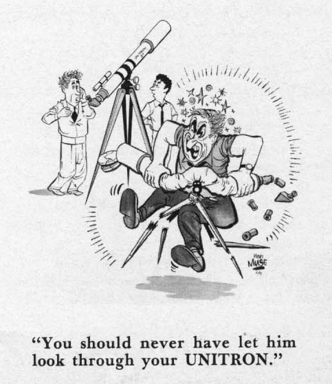
Self-explanatory
Click on images to see enlarged views (in order 204,980, 225,445, and 203,227 bytes).
Unitron developed comprehensive catalogs and hand-out literature focused on the more popular models. Unitron published their first Observers Guide and Catalog explaining each of their telescope models, their accessories, and with a brief observing guide for amateur astronomers. This was followed in 1956 by a revised and updated a forty-one (41) catalog that appeared similar but that also included customer testimonials and astrophotographs taken by Unitron owners. When we look at Unitron literature we are struck by the lack of information about the optical tubes and mounts weights and dimensions; it leaves us wondering how many people ordered a Unitron only to be shocked upon arrival by its size.
![]() The Unitron & Polarex Equatorial Refractor Telescopes Particulars
The Unitron & Polarex Equatorial Refractor Telescopes Particulars
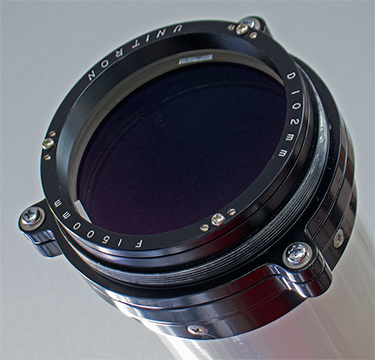
Objective Lens: Throughout the 1950’s and into the 1960’s many lens makers offered achromatic telescopes, but no other western bloc nation had a manufacturer that offered a telescope as well made and functional, so well accessorized, and with a price as moderate (given the performance) as these made by Nihon Seiko. The Nihon Seiko achromatic refracting telescope objective (front lens) employ an air spaced two lens, one group arrangement. The design derives from the Carl Zeiss E-Objektiv, a refinement of the original doublet achromatic lens that was developed by German optician Joseph von Fraunhofer (b. 6 Mar 1787, d. 7 Jun 1826). This lens employs one element made of BK7 (borosilicate crown) glass precisely matched to work with the SF10 (a high index flint) glass component. In order to attain acceptable performance the focal ratio is f/16.1, fairly long by todays standards. By the 1920’s Zeiss production included E-Objektiv 60mm telescopes similar to our Model 114 complete with gear driven altazimuth mounts, wood tripod, case, and in the customer’s choice of either f/14.2 (Telex Codeword Asedabais, No. 511071) and in f/17.5 (Asalven, No. 511071).
Click on image to see enlarged view (273,520 bytes).
Chromatism: this achromatic lens design provides a good degree of perfection of color correction (chromatism) due to the two types of glass used. It is the type of glass used that largely determines how well the color correction can be, while it is the prescription and how well the manufacturing meets that prescription that determines the other aspects.
 When observing at moderate magnifications then the primary three colors of the spectrum will appear to be at focus to the eye. However, the two types of glass used to make theses lenses can only bring two of the three primary colors to focus since not all the wavelengths pass through the lens similarly. Achromatic objectives can bring either red and green or green and blue to focus. In this lens design red and green are at focus, while blue is slightly out. So when observing contrasting objects at very high magnifications such as the limb of the Moon, a bright star against a background of space, the dark branch of a tree contrasted against a light blue sky, then the areas where dark and light objects meet will appear with a slight violet halo. The planets for example do not appear as natural in color as they might with a more advanced apochromatic objective; Jupiter and Saturn appear a bit yellowish than when viewed through the achromat than with an apochromatic system (refractor or reflecting) where they may appear milky white.
Click on the image above to view enlarged close up of the Egret where the violet fringing will be more apparent (132,351 bytes).
Optical Performance Of The Unitron 4 inch x 1,500mm Objective
Coma
Spherical
AberrrationChromatic
Aberration:G
F
E
D
C
30 nm
10 nm
2183 nm
0 nm
590 nm
740 nm
0 nm
The G violet color is farthest from focus; this is why contrasting objects observed at high magnification appear with violet halo.

Focal Ratio: as light passes through a glass lenses it is refracted, gradually bent by one lens so that it is no longer a parallel beam of light coming in from the distance but is tapering to a point within the telescope optical tube. As light passes through the first lens element it is again bent slightly by the air in the space between the lenses; note how stars twinkle as light passes through moving air layers of varying density. Then the light passes through the second element and is bent yet again. So light has to deal with four surfaces and an air space, in addition to passing through two elements of glass (Crown and Flint). The steepness of the curves of the glass impact the properties at the image plane, the point of focus. The steeper the glass curves are then issues can develop including curvature of field, spherical aberration where light from the edge of the lens may not come to focus at the same plane as light from near the center. There are modern techniques to deal with these issues (improved glass types, computer aided production of complex even aspheric curves, etc.) but up into the 1970’s lens makers preferred to keep the lens curves spherical and able to acclimate to temperature changes. This was accomplished by using thinner lenses with shallower curves thus resulting in longer focal ratios - and very long telescope tubes!
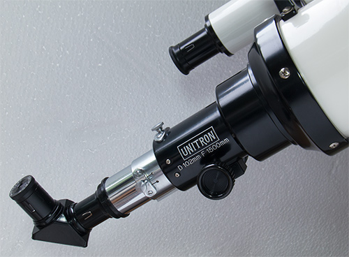
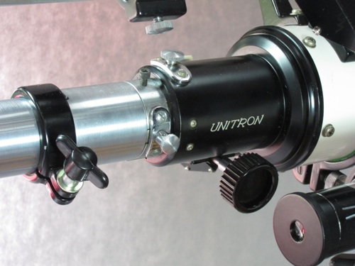
Note the stick-on Unitron label, this is as delivered in Europe on our late production Model 132 telescope. Shown with the 90-degree Star Diagonal (Zenith Prism).
Click on image to see enlarged view (233,368 bytes)
Note both setscrew locks. This is the type of focuser provided with the Unitron Model 145 telescopes (60,799 bytes).
Click on image to see enlarged view (213,237 bytes)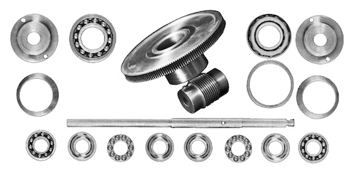 Mount Head and Tripod: among the attractive aspects of the entire product line was the value they provided with their attention to precision, rigidity, and appearance in the design of the mounts that support the telescope optical tube assembly. In these areas the Nihon Seiko products stood alone for decades. Nihon Seiko made German Equatorial Mounts and Altazimuth Mounts so most telescopes were offered in the customers choice of either mount. The mount heads are built upon machined aluminum castings that incorporated finely crafted roller bearings, worm and main gears, and other components of stainless steel. Customer who preferred a telescope dedicated to astronomy would not only have the choice of the telescope on a German Equatorial Mount, but also had the choice of more sophisticated Photographic Equatorial ensembles. The larger telescopes can barely be accommodated, even for static display without special consideration of their height. An even more impressive memory is seeing a large Unitron telescope set up and with an amazing array of finder/guide/auxiliary telescopes attached to (almost smothering) the primary telescope.
Click on images to see enlarged views (in order 187,530 then 185,918 and 199,956 bytes).
In June 2015 through the kind assistance of Mr. Albert Carcich of New Jersey, we acquired a UNIBALANCE Counterweight Set that appears as new and with original carton.
This has since been installed onto Company Seven’s Model 132 telescope exhibit.
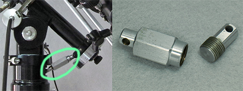 Since this elevation adjustment motion involves working against gravity, the mount head is fitted with a latitude fine adjustment mechanism to attain a more precise pole alignment. The latitude adjustment mechanism consists of a hardened stainless steel threaded worm (male) and hexagonal sleeve (female), similar to a turnbuckle, to drive the mount head tilt up or down precisely.
Click on image to see enlarged view (183,869 bytes).
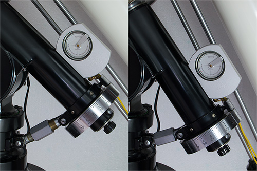 Next turn the latitude adjustment mechanism, this control can be turned by hand and is easier to do if while turning the hexagonal sleeve with one hand you gently support the telescope with your other hand doing so in a manner to reduce the load on the mount elevation bearing. The latitude adjustment mechanism has only a limited span of travel, this is dependent on the lengths of the two threaded components. So when the mount was sold new the distributor provided the appropriate mechanism for the user’s intended latitude. This was fine if you lived in one latitude range such as along the northern states of the USA or in the United Kingdom for example. But if you relocated to Florida for example, then you would need to change the assembly with one that is suitable for the lower latitude.
Click on image to see enlarged view (247,749 bytes).
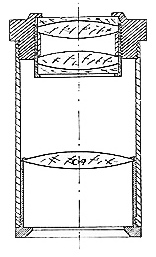 The eyepieces designs provided by Unitron included the Ramsden (sometimes termed Modified Achromatic), a design formulated in 1782 by scientific instrument maker Jesse Ramsden. The Kellner (designed b Carl Kellner in 1849) is another popular choice, basically an improved Ramsden. Both the Ramsden and Kellner are economical general purpose eyepieces that when made well satisfy most novices however, the Ramsden introduced perceptible false color that some people may wrongly attribute to originating in the telescope objective lens. Given the f/15 to f/16 focal ratios of the Unitron telescopes makes less demands of an eyepiece than faster designs, these eyepieces were suitable for most amateurs. For the more demanding clients there were optional Orthoscopic (design devised by Ernst Abbe of Carl Zeiss in 1880) eyepieces available too. The Orthoscopic is highly regarded for its uniformity of magnification (lacking distortion) across the entire field of view when used with systems of f/7 and longer. When made well the Orthoscopic provides superb contrast and definition thereby making it an optimum choice for high resolution applications including observing the planets, double stars, the Moon, etc.
As the industry changed to 1.25 eyepieces the sources of 0.965 eyepieces (Carton Optical Industries Ltd. for example) gradually discontinued production of the older standard. By this time telescope sales at Unitron were winding down anyway so there was no need to source new stock of the 0.965 eyepieces. By the mid 1980’s Unitron offered a greater selection of 1.25 inch diameter eyepieces than they offered 0.965 inch models.
* this was a 1.25 inch diameter 40mm Kellner-Monochro eyepiece, because of this larger diameter barrel it could be employed on the 2.4, 3 and 4 inch telescopes only with the UNIHEX attached.
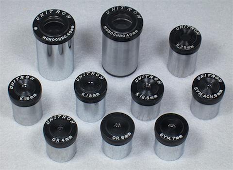
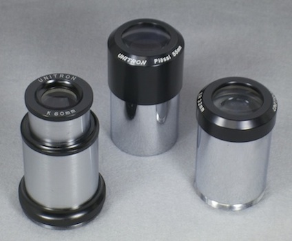
• Field of View is actual field of view as calculated for our Unitron 4 inch refractor based on our eyepiece design data and testing.
• The ER32 eyepiece was made to either slip fit into 2 inch port of a Super UNIXEX or thread-on to the Super Focuser drawtube.
• The 55 Plössl eyepiece was made to slip fit into 2 inch port of a Super UNIXEX.
• The ER32 eyepiece was made to either slip fit into 2 inch port of a Super UNIXEX or thread-on to the Super Focuser drawtube.
Make
Model
Dia.
Mag.
Design
Field of View
UNITRON
MONOCHRO.40mm
1.25"
38X
Mononchromat
0.90°
UNITRON
# MONOCHRO.40mm
1.25"
38X
Mononchromat
0.90°
UNITRON
R25mm
.965"
60X
Ramsden
0.68°
UNITRON
K25mm
.965"
60X
Kellner
0.61°
UNITRON
K18mm
.965"
83X
Kellner
0.42°
UNITRON
K13mm
.965"
120X
Kellner
0.40°
UNITRON
K12.5mm
.965"
120X
Kellner
0.31°
UNITRON
SYM. ACH. 9mm
.965"
167X
Achromatized Symmetrical
0.23°
UNITRON
SYM. ACH. 7mm
.965"
214X
Achromatized Symmetrical
0.18°
UNITRON
OR 6mm
.965"
250X
Orthoscopic
0.15°
UNITRON
OR 4mm
.965"
375X
Orthoscopic
0.13°
UNITRON
K60
25X
2"
Kellner
1.52°
UNITRON
55mm
27X
2"
Plössl
1.45°
UNITRON
ER32mm
61X
2"
Erfle
1.28°
![]() The Glory Days of Space and Unitron
The Glory Days of Space and Unitron
 While the 1950’s were prosperous years for Unitron, in 1957 astronomy fever erupted with the launch of the Russian satellite Sputnik. The space race was on, and this drew national interest to space and science. The US space program was in full swing, and from it came real heroes and the country was unified with a national purpose. People and screen writers had imagination; television programs about astronauts, space and a bright future were on in prime time including Outer Limits, Twilight Zone, Lost In Space, My Favorite Martian, The Jetsons cartoon, I Dream of Jeannie, and of course Star Trek. Countless notable personalities including talk show host Johnny Carson, author Arthur C. Clarke, actor Marlon Brando, brought telescopes to the public attention. Even Dr. Wernher Von Braun, one of the preeminent rocket engineers of the 20th century, looked up to the Moon through his Questar 3-½ telescope. All while Unitron prospered.
Click on image to see an enlarged view (762,206 bytes).
 Unitron did not have much time to enjoy the fruits of the growing market since there were ominous signs on the horizon. Among these were an increase of tensions regarding competition and trade issues between the USA and Japan. These came to the limelight in 1969 when President Nixon and Japanese Prime Minister Sato met in Washington, DC on November 19, 20 and 21, to discuss world events and matters of mutual interests to the United States and Japan. The meetings included discussions about trade imbalances and trade liberalization - making Japan’s markets more accessible for US products; this was not to be the last time these matters would come up so publicly. The discussions closed with an statement where parties agreed to try harder (as usual when US trade representatives meet foreign delegations) to address the large imbalances in trade and payments between the USA and Japan. But more about this later.
*Let’s not overlook the Carl Zeiss company was there well before the others. By 1886 Zeiss was manufacturing microscope objectives employing calcium fluorite (CaF2) elements. And their subsidiary Schott pioneered the making of high grade synthetic calcium fluorite. However, Zeiss had not really pressed their Apo lens technology into the amateur telescope market - yet.
The worsening condition of the US economy lead to high interest rates. This combined with the energy crises and rising costs during the 1977 to 1981 term of President Jimmy Carter meant there was more and more competition in the USA for fewer sales. As we have observed again after the financial crises of the Wall Street bailouts, the housing bubble burst of the recent years: most people NEED milk and gasoline, they do not need telescopes.
Alongside is Vixen 102FL 4 inch f/9 Fluorite Apo telescope shown on Vixen GP equatorial mount and aluminum tripod (retracted), image size 13,789 bytes.
Telescope images are scaled to show the approximate differences in physical size.

of that good old-fashioned American capitalism? (27,364 and 24,152 bytes).
 The decline of Japanese dominance in the US market under the administration of President Ronald W. Reagan, high spending in some areas, various exemptions to planned budget cuts and the loss of federal revenue from tax cuts created difficulties in balancing the federal budget. As a result, the government borrowed extensively to pay its bills issuing Bonds and the like. Government debt about tripled from 1980 to 1988. Much of this money came from abroad, especially from Japan. Borrowing money to pay the debt caused the government to spend a greater proportion of its budget on interest payments for loans. The budget deficit kept interest rates so high that the value of the dollar soared in relation to major foreign currencies. Consumer spending for manufactured products grew, but this was mainly spent for inexpensive imports. As a result the United States further increased its foreign debt throughout the 1980s by spending more on imported goods than it earned from exports. The U.S. trade deficit climbed from $24.2 billion in 1980 to $152.7 billion in 1986. By 1986 with James Baker as Treasury Secretary, an effort began to reduce foreign indebtedness, the government devalued the dollar. Devaluation, which lowered the value of the dollar in relation to foreign currency, made American products less expensive and therefore more desirable in foreign markets. During the next few years, the dollar declined in value by over 40% on a trade-weighted basis and encouraged a major revival of US exports. However, devaluation failed to erase the trade deficit.
We would see the steady decline in US buying power accelerate so that by 1988 the exchange rates were at about 128 Yen per dollar!
![]() UNITRON Model 132 4 inch Equatorial Refractor Specifications:
UNITRON Model 132 4 inch Equatorial Refractor Specifications:
Optical Tube Assembly German Equatorial Mount with Tripod
Objective Lens Aperture
3.9 inches (99.80 mm)
Focal Length
59.05 inches (1500 mm)
Focal Ratio
f/15
Coatings
Multilayer Anti-reflection
Optical Tube Length Overall (Incl. Diagonal)
64 inches (162.56 cm)
Optical Tube Diameter
4-⅜ inch diameter (111.12 mm)
Dew Shield Diameter
4-55⁄64 inch diameter (123.5mm)
Finder (Standard)
10x 40mm, inline view
Focuser
1.25 inch Dia., Rack & Pinion
Telescope OTA Weight
10.4 lbs. / 4.7 kg.
Telescope OTA Wood Case
17.0 lbs. (7.7 kg)
OTA Origin
Made in Japan
Mount Head and Tripod Height (top of Saddle at our Latitude)
63-½ inches (161.3 cm)
Controls
Manual Geared
Return (Decl)
Spring Loaded Piston
Clutch (RA & Decl)
Manual
Mount with Tripod Set Weight
42.2 lbs. (1.69 kg)
Wood Tripod & Journal Height
58-½ inches (148.6 cm)
Tripod Brace Weight
1 lb. 3 oz. (.54 kg)
Mount Head Wood Case
14.6 lbs. (6.6 kg)
Mount Origin
Made in Japan
Complete Telescope & Mount Set Weight
64 lbs. (29.1 kg)
![]() Additional Reading From Our Unitron Archives:
Additional Reading From Our Unitron Archives:
![]()
Contents Copyright 2011-2017 Company Seven and respective contributors - All Rights Reserved


