|
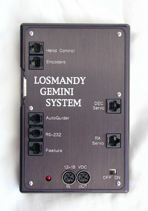
1. Disconnect all cables (including power) from the Gemini.
2. Remove the cover (1/16" Allen wrench needed),
3. Rene Georlich has never experienced or heard of an EPROM dying because of statical discharges. Nevertheless, touch the water pipe or something metallic connected to the ground before replacing the EPROM.
4. The EPROM is socketed in the Gemini, you need a screw driver (around 5 mm) to insert it between the socket and the EPROM
(NOT between socket and board!) and gently lever it up from the left and right side by turning the screw driver slowly. It comes out easily.
5. Save the old chip, it can be erased with UV light and reprogrammed many times.
6. Unpack the new EPROM and plug it into the socket. The direction is MOST important! Look at the notch at the small side, there is also a notch printed at the silk screen of the printed circuit board, to the left side. They must correspond to each other. The pins of the Level 2 EPROM are already adjusted by me with a special tool, don't use force if they do not fit into the holes immediately, use your finger nail sliding along the pins to get all of them into the socket.
7. Once all pins are in their respective holes, press the EPROM with both thumbs into the socket. Again, not much force is needed!
8. Check again if the notches of EPROM and silk screen print are on the same (left) side!!
9. Close the cover.
10. Check if the Gemini boots up by connecting the power cord (and the DeLuxe HC if no display is onboard) and switching the unit on. All EPROMs are tested to boot up the Gemini prior to shipping!
11. Look at the startup message. The EPROM Level/Version/Serial Number is displayed. Depending upon your previous software version, "CMOS resetted" may be appended. If not, please use the Gemini's Setup->Restore Defaults to change the setting to their default values and initialize the internal pointers of the User Catalog and the log.
12. Input your setup values. You can use the optional Gemini Control software program to do this.
13. Set up your telescope's mount, activate Gemini and then set the mount movement Safety Limits.
Procedure last modified by Rene Goerlich: November 12, 2001.
|
![]() C-7 News
C-7 News ![]() Consignment
Consignment ![]() Library
Library ![]() Products & Services
Products & Services ![]() Product Lines
Product Lines ![]() Order
Order ![]() Search C7.com
Search C7.com
![]() Distribution
Distribution
![]() News
News ![]() Notes & Interesting Articles
Notes & Interesting Articles ![]() Pricing
Pricing
![]() Products
Products


