|
Products
and Services |
|||||||||||||||||||||||||||||||||||||||||||||||||||||||||||||||||||||||||||||||||||
|
|
| ||||||||||||||||||||||||||||||||||||||||||||||||||||||||||||||||||||||||||||||||||
 |
What is it?
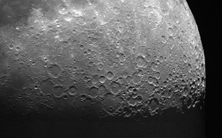 |
Video STV
image of the moon taken through a 5" f/6 |
The STV is an entirely new concept for video imaging and autoguiding. The camera is a hybrid design that combines the best of both traditional video technology and cooled integrating digital CCD camera technology. The result is a cooled integrating digital video camera capable of recording much fainter objects than traditional video cameras and at the same time give the performance of a cooled integrating CCD camera in a self-contained unit that is as easy to use as a video camera at the telescope.
Modern astronomical CCD cameras use cooled detectors to lower the dark current and the electronics are designed to take (integrate) single exposures up to an hour long. This technology results in very sensitive cameras capable of reaching greater than 20th magnitude with typical amateur telescopes from backyard sites. Our web site is full of beautiful images from amateurs all over the world who have captured many dim deep space objects with amazing detail. But CCD imaging is not as simple as using a video camera. One must use a computer of some kind at the telescope to control the CCD camera and save the images. This extra bit of equipment requirement and additional power cords, etc., is often just enough to make CCD imaging too much of a hassle for some. However, with the STV, this is also no longer a problem. No computer is required to use the STV as an autoguider or an imager.
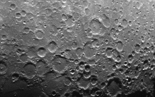 |
| Video STV
image of the moon taken through a 5" f/6 telescope with 0.01 second exposures and zoom display mode. |
Video astronomy is a popular pursuit because nearly everyone is familiar with video cameras. The idea of putting a video camera at the eyepiece of a telescope and seeing the results on a TV monitor is very exciting. It is an easy way to share the views of the night sky with friends and family. The viewing is comfortable and the images can be recorded on tape. But one limitation of typical video astronomy is the inability of even "low light" video cameras to capture faint nebula, galaxies or stars dimmer than about 9th or 10th magnitude through an 8" scope. By cooling the detectors and designing the cameras to take long exposures (integrate) over many minutes, modern astronomical CCD cameras like the ST-7 have overcome much of the limitation of video astronomy. However, video cameras remain an interesting accessory for amateur astronomers because of their relative ease of use, despite their inability to record dim objects. This limitation of typical video cameras is a result of the common video format. Video cameras cannot usually take exposures longer than 1/30th of a second. Even if they could, the CCD detectors used in typical video cameras are not cooled. The dark current that would build up in longer exposures would result in noisy looking images. The only way to increase the sensitivity of typical video cameras up to now has been to add an image intensifier (e.g., night vision scope) between the camera and the telescope. This works, to a degree. But the images are usually very grainy and suffer from poor resolution. The result is that amateur video astronomy is generally limited to imaging bright objects like the moon and planets. This problem has been solved in the STV.
|
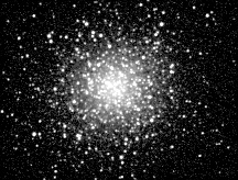
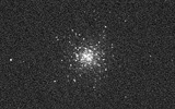
Video STV
image of M13 taken |
By utilizing a cooled detector and designing all new electronics around a DSP (digital signal processor) we have been able to achieve the performance of a cooled integrating astronomical CCD camera in a more traditional video format. Exposures from 1/1000th of a second to 600 seconds are possible. The video output can be viewed on the built-in LCD display or on any external video monitor. We estimate the STV will reach 14th magnitude stars with one second integrations through an 8" SCT - and 18th magnitude in 60 seconds.
Objects that are impossible to capture with a typical low light video camera are easy targets for the STV. Globular clusters, nebula and galaxies are easily displayed on a video monitor, recorded on video tape or captured as digital image files. One simply increases the exposure until the objects are visible and presses a button to capture the image.
How does it work?
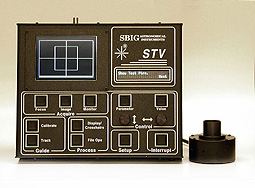
The STV operates very much like a traditional video camera but with some important distinctions. The STV consists of a camera head and a control box (click on the image at the top of this page to see a full size image of the STV). The camera head contains the detector, some electronics and the thermoelectric cooler. The head is connected to the control box by a 15 foot cable. The control box requires 12VDC. The camera head has a 1.25" nose piece which means it will fit any telescope or finder scope that accepts 1.25" eyepieces. It can be used in place of an eyepiece in the main telescope, or it can be used as an "electronic" eyepiece in a finder scope. When used as an autoguider, the STV head will fit in a separate guide scope or may be used in place of a cross-hair guiding eyepiece in most typical off-axis guider assemblies. And, since the STV is approximately 30 times as sensitive as an ST-4 autoguider, finding suitable guide stars in an off-axis guider through the main OTA will be a much easier task.
 |
Of course, no external computer or video display is required to operate the STV, and when used as an autoguider, the optional
built-in 5" LCD display is not needed although it may make finding and focusing stars
much easier. The STV will have a
2 line x 24 character alphanumeric display will show all the information needed to operate
as a stand alone autoguider.
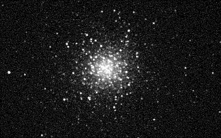 |
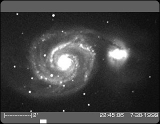
| Video STV image of M13
taken through an 8" SCT at f/3.5 using an SBIG focal reducer and 5 second exposure. Normal display mode. |
What does it do?
The STV is a Digital Integrating Video Camera and Autoguider:
Digital Integrating Video: The STV will take digital video images and instantly display them on the built-in 5" LCD display or on any external video monitor. "Integrating" means that the camera is capable of exposure times much longer than 1/30th of a second. The images can be recorded on video tape. The update rate for the video display depends on the mode selected and of course the length of the exposure. If one selects exposures longer than say one second, the display will not update until the exposure is completed. However, the previous frame remains on the video display until it is replaced by a new image. For short exposures (e.g., 1/1000th of a second) the display will update as fast as 16 frames per second.
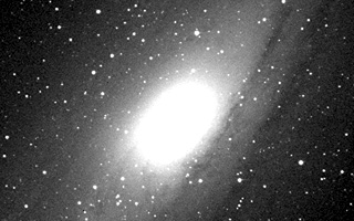 |
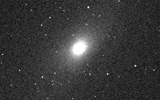
| Video STV image of M31,
Andromeda Galaxy, taken through a Celestron 8" Fastar telescope at f/2 with 30 second exposures and normal display mode. |
Camera: In addition to digital video output, the STV will take and store digital images in its on-board memory just like a digital camera. Stored images may be downloaded to a computer at a later time. If one wishes to connect a computer to the STV while it is in operation, digital images may be downloaded to the computer with the push of a button on the STV control box. Once transferred to a computer, the images may be viewed, processed, etc., with CCDOPS software or exported to a popular image file format such as TIFF for use with third party image processing software.
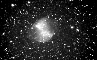 |
| Video STV image of M27
taken through an 8" SCT at f/3.5 using the FR5C focal reducer and 60 second exposure. Normal display mode. |
Autoguider: The STV will also autoguide! We now have 10
years of experience making the leading autoguider in the world for astrophotography and
this experience has taught us a thing or two about how to make the task a little easier.
All these improvements are incorporated in the STV. Believe it or not this was its sole
intended purpose when it was first put on the drawing board two years ago. It has
obviously evolved far beyond just an autoguider - but these functions are still
there. As a stand alone autoguider (no computer required) the STV will reach several magnitudes fainter than
the old "work horse" ST-4.
 |
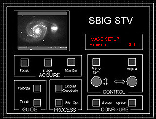 |
| The
STV is a video camera / autoguider that is entirely self-contained (drawing at
right). Images may be viewed on the optional built-in 5" LCD video display or
they may be viewed on any video monitor or TV accepting normal video input (simulated on
left). The STV also has a built-in 2 line x 24 character alphanumeric display with
red characters on black background. The alphanumeric display provides menu and mode
information for ease of use without a computer. The alphanumeric display also shows
data when measuring stellar magnitudes, separation, etc., in analysis mode. In DISPLAY mode, the video monitor shows the following information on the TV screen: (a) the video image, (b) the time and date, (c) a scale bar in arc seconds or arc minutes depending on your telescope set up parameters and the zoom mode you select and (d) a moving cursor at the bottom the screen indicating exposures in progress (as in continuous update mode). |
|
 |
 |
Both M13 and M31are easily viewed in these one second exposures
through an 8" Fastar telescope..
Electronic Finder: If you already have an astronomical CCD camera and have difficulty placing objects on the detector because they can't be seen, the STV will make a great accessory as an "electronic finder." If placed at the eyepiece tube of a finder scope the STV can record and display star fields with limiting magnitudes comparable to common finder charts or the exposure can be increased until the deep space object is actually seen through the finder scope. This can eliminate the need for removing the main CCD camera from the telescope to find and center objects on its detector (see diagram below).
Seeing Monitor:
The STV will generate a graph on the video display showing the seeing conditions
as a function of the FWHM of star images as sampled every 2/10ths of a second.
Telescope Drive Monitor:
The STV will generate a graph on the video display showing the error in RA and
DEC as your telescope drive operates in real time.
The examples below demonstrate some of the various display modes one sees on a TV monitor and on the backlit digital display when using the STV. On an actual video display, the area outside the image is set to black but is shown as grey in these examples for illustration purposes. The time and date appear outside the image area but on the video frame when viewing or recording images on video tape. The time and date are not displayed if the image is downloaded to a computer but are saved in the header information just as they are in other SBIG image files.
|
O O O O |
IMAGE
SETUP |
 |
O O O O |
A partial frame mode with either normal or zoom display may be selected for faster
focusing. This mode results is update rates about 2X faster than normal imaging
mode. The time and date are not displayed in focus or analysis mode.
FOCUS
SETUP |
 |
O O O O |
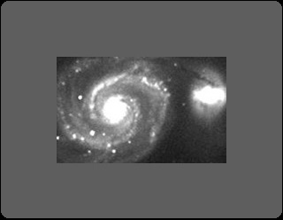
In WIDE FIELD display mode, the full 656 x 480 pixel array is binned 3x3 and displayed so the entire field of view of the detector is visible on the video monitor. The time and date are displayed in the lower right hand corner of the video frame outside the image area.
IMAGE
SETUP |
|
O O O O |
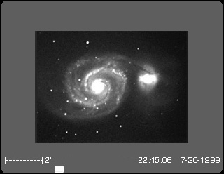
In NORMAL display mode a 640 x 400 portion of the detector is
binned 2x2 and displayed so that the full width of the image fills the width of the video
monitor. The time and date are displayed in the lower right hand corner of the frame
outside the image area.
IMAGE
SETUP |
 |
O O O O |
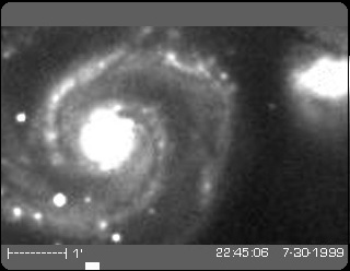
In ZOOM display mode the central 320 x 200 portion of the
detector is displayed unbinned so that the width of the image fills the width of the video
monitor. The time and date are displayed in the lower right hand corner of the
frame outside the image area.
IMAGE
SETUP |
 |
O O O O |
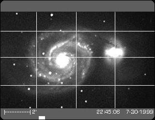
One unique imaging mode is the grid display. In this mode a video overlay of 6
lines yields 9 handy cross hairs that may be used for visual placement of guide stars when
using the STV for manual guiding. The time and date are
displayed in the lower right hand corner of the frame outside the image area.
STV
SETUP |
 |
O O O O |
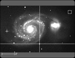
In ANALYSIS mode, the alphanumeric display provides several types of information including the X,Y location of the moving cross-hair as well as the value of the pixel under the cross-hair and the average value. When an image is captured the display does not update. Large movable cross-hairs superimposed on the video monitor are controlled by two rotary dials on the STV. One places the intersection anywhere on the image and presses a button. The first selection measures the background and automatically marks the location with a box. The large cross hairs are then moved to a star or other location and the digital display automatically gives the magnitude of any star placed under the cross hairs. If the select button is pressed again, this second location is marked by a small cross hair. When the large cross hairs are moved to a third location the digital readout on the STV automatically displays the separation in arc seconds from the previous star or location marked by the small cross-hairs.
DISPLAY
Mag=+12.76 |
To see more sample images click here.
In addition to the various display modes described above, the STV has several analytical modes which allow you to measure seeing, periodic error and guiding accuracy:
 |
 |
Periodic Error Monitor |
Seeing Monitor |
 |
 |
Sample guiding errors - unguided |
Sample guiding errors - fast guiding |
Focal Reducer: Our custom focal reducer / eFinder assembly is a highly recommended accessory. It will screw into the nose piece of the STV to increase the field of view and decrease the effective f/ratio of your optical system. It is designed to be used on systems with focal ratios of F/15 to F/6.3. For example, when used with and without the extension tube the focal reducer will yield the following focal ratios:
| Focal ratio of parent system | F/10 | F/6.3 |
| Resulting focal ratio without extension tube | F/5.95 | F/3.75 |
| Resulting focal ratio with extension tube | F/3.75 |
eFinder Assembly: The focal reducer lens is also designed to work as a convenient wide field finder lens when placed at the correct distance from the CCD. The eFinder assembly screws into the STV head in place of the 1.25" nosepiece and holds the focal reducer lens at the correct distance. In this configuration the STV becomes a very sensitive "electronic finder" with a field of view of approximately 2.7 degrees. Any star in the Uranometria catalog can be seen in a three second exposure through the eFinder lens. In addition, the STV will autoguide with this lens assembly to an accuracy of less than one arcsecond, eliminating the need for a separate guide scope.
|
| STV Features and Specifications: | |
| Complete Stand Alone
Operation - Video Imager with on board video display or external video monitor - Autoguider (30 times more sensitive than an ST-4) - Digital Imager (using on board memory for image storage) |
Self-contained Control
Panel: - 11 button keyboard with two rotary switches for setting numbers - 2 line x 24 character vacuum fluorescent digital display - 5 inch diagonal LCD TV screen built in (optional) |
| Video or Digital Image
Formats - Video output for connection to any TV or VCR - RS232 output for downloading digital images to any computer |
Focus Mode: - sub-frame and electronic zoom features |
| Image Mode: - exposure times from 0.001 to 600 seconds - full or zoom format - single or continuous update - Track and Accumulate (Patented) |
Monitor Mode: - measure atmospheric seeing - measure telescope drive periodic error |
| Display/Crosshairs Mode: - adjust display brightness and contrast - measure star magnitudes - measure stellar separations |
Track Mode: - automatic or user select - guide to: current position, last position, displayed cursor or selected star - aggressiveness 0.1 to 2.0 |
| File I/O Mode: - display image - save file to memory - download displayed image - download all images in memory - erase displayed image - erase all images in memory |
Calibrate Mode: - automatic or user select - exposure times 0.01 to 99.9 seconds - movement: incremental or single - calibration time: 0.1 to 9.99 - active relays: X & Y, X only, Y only - view calibration results |
| Set Up Mode: - set time / date - show grid - night vision (on/off) - video display (yes/no) - chose units of measure (in/cm) - set focal length - set aperture - telescope type (refractor or reflector) - set site ID (1 to 155) - show video test pattern 1 (box to show size) - show video test pattern 2 (gray scale, 0 to max) - set video offset for dark level |
Option Mode: - self test - open shutter - close shutter - run shutter - show CCD temp - measure image (average and rms noise) |
| Video Output: - NTSC Standard - 525 horizontal lines with 720 pixels / line - PAL Standard available as a menu option |
CCD: - Texas Instruments TC-237 - High Sensitivity Frame Transfer (electronic shutter) CCD - 656 x 480 pixels @ 7.4 microns square |
| Image Modes: - Normal = 640 x 480 binned 2x2 - Wide = 656 x 480 binned 3x3 - Zoom = 320 x 200 binned 1x1 |
Image bit depth: - 10 bits for 1x1 binning mode - Up to 16 bits for other binning modes and Track and Accumulate images |
| CPU Weight: 4lb (1.8kg) with LCD, 3.2lb (1.4kg) without LCD | Head Weight: 16oz (0.4kg) |
| CPU Dimensions: 11.6 x 9.4 x 2.6 inches (29.5 x 23.7 x 6.7 cm) | Head Dimensions: 3.25 x 1.75 inches (8.3 x 4.4 cm) |
| Specifications, prices and accessory packages subject to change without notice. | |
This is the first cooled integrating video CCD camera and autoguider offered to the
amateur astronomy market. The Standard STV includes the
thermoelectrically cooled camera head with standard T-threads, removable 1.25" nose
piece, control box with alphanumeric display, 110VAC adapter, and internal neutral density
filter. The Deluxe STV includes the all the standard items plus a
built-in 5" LCD video display, tripod mounting foot and a custom hard carrying case.