Optec MAXfield 0.33X Three Element Telecompressor FAQ (Frequently Asked Questions) Page
 Also available in Adobe PDF Format (1,185,914 Bytes>
 What is the MAXfield?
 The MAXfield telecompressor is a three-element lens system designed to work specifically with Schmidt-Cassegrain f/10 telescopes (SCT's) and medium to small format CCD cameras. The telecompression ratio is
0.33x, so an f/10 system becomes f/3.3 and an f/11 system becomes f/3.6. Basically, the MAXfield is a three-part system - a telescope mount threads onto the 2-inch thread on the back of the SCT - a lens mount which holds the lens system - and a camera mount which
adapts the lens system to a particular camera. The picture below shows the three parts of
the MAXfield telecompressor system.
The MAXfield telecompressor is a three-element lens system designed to work specifically with Schmidt-Cassegrain f/10 telescopes (SCT's) and medium to small format CCD cameras. The telecompression ratio is
0.33x, so an f/10 system becomes f/3.3 and an f/11 system becomes f/3.6. Basically, the MAXfield is a three-part system - a telescope mount threads onto the 2-inch thread on the back of the SCT - a lens mount which holds the lens system - and a camera mount which
adapts the lens system to a particular camera. The picture below shows the three parts of
the MAXfield telecompressor system.
In some cases the telescope mount is not needed. Since the lens system will fit into any
2-inch focuser, you may be able to order the MAXfield 2"(our stock no. 17402)
and save a little money.
Can the MAXfield be used with any telescope
other than an f/10 SCT?
The MAXfield will work fine with an f/11 C-14
SCT provided the telescope has enough back-focus. Of course at 0.33x, an f/11 system
becomes f/3.6. Any SCT with an f-ratio of 10 or higher should work fine. Takahashi has an
f/12 SCT available that should work with the MAXfield provided there is enough back-focus.
The MAXfield has been used successfully with a classical cassegrain [see Optec's Image Gallery], but has not been tested on a
Maksutov cassegrain. The design corrects for the coma of an SCT which tends to greater
than a Maksutov (which is essentially coma-free).
O.K., how much is "enough"
back-focus?
Our calculations indicate that the required
back focus is about 195mm. There is a fairly easy way to check this distance with your own
telescope. First remove the visual back and place a blank white card 195mm (about 7
5/8") behind the last thread of the telescope's threaded mount. If you can achieve
focus from an object at infinity (the moon works well for this), then your telescope has
"enough" back focus.
Can I couple the MAXfield with an f/6.3
telecompressor to get an incredible f/2 system?!?
No. (It may work mechanically, but optically
you'll really be disappointed.)
How does the MAXfield attach to the back of
the telescope?
When the standard MAXfield is
specified (our stock no. 17400) the MAXfield is shipped with a telescope mount which
threads directly onto the rear cell of the SCT. The MAXfield lens assembly will fit
directly into a 2" focuser such as the motorized NGF-S by JMI. In fact, owners of the
NGF-S can save a few dollars by ordering the MAXfield 2" (our stock no. 17402)
which does not include the telescope mount.
Explain the difference
between the MAXfield 2" and the standard MAXfield again.
The standard MAXfield includes both the
telescope mount and the lens assembly while the MAXfield 2" includes only the
lens assembly. In the drawing below the telescope mount is shown in red, the lens assembly
is light blue and the camera mount is purple. The camera faceplate (ST-7 in this case) is
yellow. Note that the 2" filters (shown in blue) thread into the front of the lens
assembly.
Right-click to view at full resolution.
How much vignetting will there be using the
MAXfield?
Of course, that depends on a number of
factors. The MAXfield will provide an 11mm diameter unvignetted image which will cover
most chips in the small to medium size class. In practice, you may see some vignetting
depending on the telescope as well as the camera. With our ST-6 camera (TC-241 CCD with a
diagonal of 11mm) we see about 8% vignetting using the standard 2" rear cell mount on
our 10" SCT. The standard SCT rear cell thread is an (approximately) 2-inch diameter
male thread. On the 10" and larger class telescopes the rear cell can be removed to
expose an even larger 3-inch diameter thread. Using the JMI Large-Format Adapter with an
NGF-S focuser, we virtually eliminated all vignetting in our system.
Is vignetting a problem?
Not really, since good flat-fielding will
remove the negative effects of a vignetted image.
Why are different mounting plates needed for
different CCD cameras?
Each CCD camera has a different specification
for important parameters such as optical distance to the CCD chip and camera
faceplate mount. Even different models from the same manufacturer may place the CCD chip
at a different depths within the camera head even though the physical mount is the same
(i.e. cameras using a T-mount thread).
What is meant by optical distance to the
CCD?
The optical distance takes into consideration
the index of refraction of any glass that may be in the optical path. For instance, nearly
all cameras has some sort of cover glass used to seal the CCD chamber. The thickness of
this glass may vary from manufacturer to manufacturer (and even between models of the same
manufacturer) and must be compensated for in the mounting plate. Basically, the
introduction of flat glass into the optical path will increase the optical distance to the
chip. In other words, even though the CCD may be a known physical distance from the
faceplate, the optical distance will usually be further. It is this optical distance that
we are most concerned with.
The T-thread seems to be a new standard
with CCD cameras. Why can't you have just one mounting plate?
Again, the reason is that the optical
distance to the CCD varies with different CCD cameras. This difference in spacing can
usually be accommodated for by simply re-focusing at f/10. However, at f/3.3 focusing is
critical. Moving the CCD chip as little as 1mm can degrade the edge sharpness. The images
below demonstrate how critical the focusing can be. The image on the left was made at the
optimal focus. The image on the right was made after increasing the spacing by just 1mm.
[Note the star images in the lower left corners of each image.]

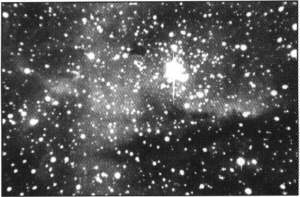
Image taken at the proper optical distance. (left) --- Same image with CCD moved just
1mm. (right)
The images above were taken by Dennis di Cicco for his review of the MAXfield in the Fall
1995 issue of CCD Astronomy
magazine. Reprints of this review are available by mail from Optec .
If spacing is so critical, exactly what is
the optimal distance from the MAXfield to the CCD chip?
For best performance and to achieve a
magnification of 0.33x, the CCD should be placed at an optical distance of 29.7mm behind
the center of the rear lens element of the MAXfield. Of course, each of the MAXfield
camera mounts ensures this optical distance is maintained. Simply order the correct
mounting kit with your MAXfield to match your CCD camera.
What if there isn't a mounting plate to
support my camera?
Call us or send an email with your camera details. We're constantly
striving to add new mounts to our list of supported cameras.
How does the MAXfield
perform with the smaller pixel cameras?
The two images of M13 below were taken the
same night using the MAXfield and our 10" LX-200. The image on the left was taken
with the ST-6 and the image on the right was taken with the ST-5. Each is a 30 second
exposure and each has been scaled logarithmically. Note the difference in plate scale due
to the physical size of the CCD's used in each camera.
 _
_
M13 image taken with the MAXfield and ST-6 camera. (left) --- M13 image taken with the
MAXfield and ST-5 camera.(right)
The M13 images above are shown at a 1:1 scaling. That is, each pixel from the CCD is
represented by one pixel on your monitor. The following table outlines the differences
between the two cameras. As you can see, the CCD used in the ST-5 camera is only about
1/3rd the size of the ST-6 CCD, yet still has nearly the same number of pixels. Of course,
each pixel is correspondingly smaller.
| Camera: |
ST-5 |
ST-6 |
| CCD chip: |
TC255 |
TC241 |
| Physical size: |
3.2 x 2.4mm |
8.6 x 6.5mm |
| Number of pixels: |
320 x 240 |
375 x 242 |
| Pixel size: |
10 x 10 micron |
23 x 27 micron |
The KAF-0400 CCD chip used in the ST-7 camera has 9 x 9 micron pixels and is capable of 2
x 2 and 3 x 3 binning. Results with the MAXfield using the ST-7 would be similar to the
ST-5 image when not binned and similar to the ST-6 image when binned 3 x 3. Refer to the
Winter 1995 issue of CCD Astronomy for an excellent discussion of pixel
size, signal-to-noise ratios, and "Optimizing a CCD Imaging System" [page 14].
So, which CCD chip size is
really better, big pixels or little pixels?
Ah, the Great Pixel Debate. This is a
hotly debated topic among many user groups and mailing lists. Without going too deeply
into the subject, we'd like to offer the images below (which are really just scaled
comparisons of the images above) to show that the MAXfield will perform equally well with
small pixels or big pixels (though we prefer the image on the right.) You make your own
judgement.
 _
_
Scaled and cropped ST-6 image using MAXfield. (left) --- Comparison ST-5 image taken
with the MAXfield.(right)
The images above are slightly out of rotational alignment (with respect to each other) and
the logarithmic scaling may not have been identical. To be fair to the large pixel cameras
we really ought to provide another comparison set of, say, a faint nebula using the same
exposure time and identical processing. Theory says the ST-6 would provide a better image
in that case. (But heck, we still like the image on the right.)
Are there any cameras that cannot be used
with the MAXfield?
Cameras using CCD chips larger than 11mm
(diagonal measurement) would certainly be vignetted. The CompuScope (ISIS, Inc.) cameras
include a built-in filter wheel that doesn't allow enough back-focus for the MAXfield.
We're presently working on additional camera mounts and always appreciate any customer
feedback.
Speaking of filters, can filter wheels be
used with the MAXfield?
Unfortunately, with the limited back focus
there isn't room for filters behind the MAXfield lens system. The front of the 2"
lens assembly, however, is threaded for manual insertion of 48mm filters. Optec supplies
filters for tri-color work, but any 48mm photographic or deepsky/LPR filter should fit
into the front of the MAXfield.
Exactly how are the 2" filters used
with the MAXfield?
After attaching a mounting plate to your
camera, the lens mount is secured to the camera mounting plate with setscrews. (These
setscrews allow rotation of the camera relative to the telescope for composing an image.)
This camera/MAXfield assembly can now be inserted into the telescope mount (or NGF-S
focuser) and is held in place with thumbscrews. By holding the camera and loosening the
thumbscrews, you can withdraw the camera and telecompressor to change filters. Thread a
new filter onto the front of the lens mount and re-insert the whole assembly back into the
telescope mount. The whole process takes about 30 seconds.
Changing filters sounds like a pain. How do
you insure proper registration of the camera between filter changes?
When changing filters it is necessary to
remove the camera and MAXfield from the telescope mount. A small registration pin
protrudes from the telescope mount. By lining up a small hole on the flange of the
MAXfield lens mount with this pin, you can easily register the two images between filter
changes.
Sorry, but changing filters still sounds
like a pain. Isn't there an easier way?
O.K., O.K.. Because of the great demand for
filter wheel compatibility we've developed the MAXfilter 2". This is a three
filter position system which uses a highly repeatable stepper motor for accurate
registration. The MAXfilter 2" uses 2" (well, actually 50mm) filters and
is fully compatible with the SBIG CFW-8 filter wheel, except that it has only three
filters. To get around this limitation the 3-position filter slider can be quickly and
easily removed and replaced with a second or third filter slider. The neat thing about
this setup is that you don't have to remove the camera or telecompressor to change filter
bars (or sliders as we like to call them). Swapping out filter sliders takes about 30
seconds and doesn't even require re-focusing (unless you use filters of different
thicknesses). Check out the MAXfilter 2" page at http://www.optecinc.com/astronomy/products/maxfilter.html.
Which filters are recommended?
We recommend that a pale yellow (#12) filter
be used to remove an undesirable chromatic difference. The #12 Yellow cuts off all light
below about 480nm or so to completely eliminate this problem. Remember that the MAXfield
design was optimized for the peak spectral response of the CCD sensor - from about 550nm
to 850nm with additional correction into the near infrared. The trade-off was the color
correction below 500nm.
What exactly does this
chromatic difference look like?
The image of NGC 6888 below left was taken
without a filter and shows the chromatic difference in the edge stars. The image at right
was the same exposure length with a #12 Yellow filter in place. Look carefully at the
stars near the corners of each image to get a feel for the differences between the
filtered and unfiltered images. Remember that the chromatic difference is more apparent in
hot, blue stars.
 -
-
Unfiltered image of NGC 6888.(left) --- The same image with #12 Yellow filter in
place (right).
Each image above was 30 second exposure using an ST-6 camera mounted on a 10"
Meade SCT. Optical design software shows the chromatic difference in the series of images
below. The leftmost image shows the blur spot of a star at infinity directly on-axis. The
middle image shows the same star at about 70% (4mm off-axis) of the full field and the
rightmost image shows the star at the edge of field (5.5mm off-axis). Note the scale is in
millimeters (right-click for full resolution). As you can see in the off-axis images, most
of the blue light (435 nm) is focused farther from the axis than the rest of the star's
light. This blue light shows up in the actual unfiltered image above, but not in the image
filtered with a #12 Yellow.
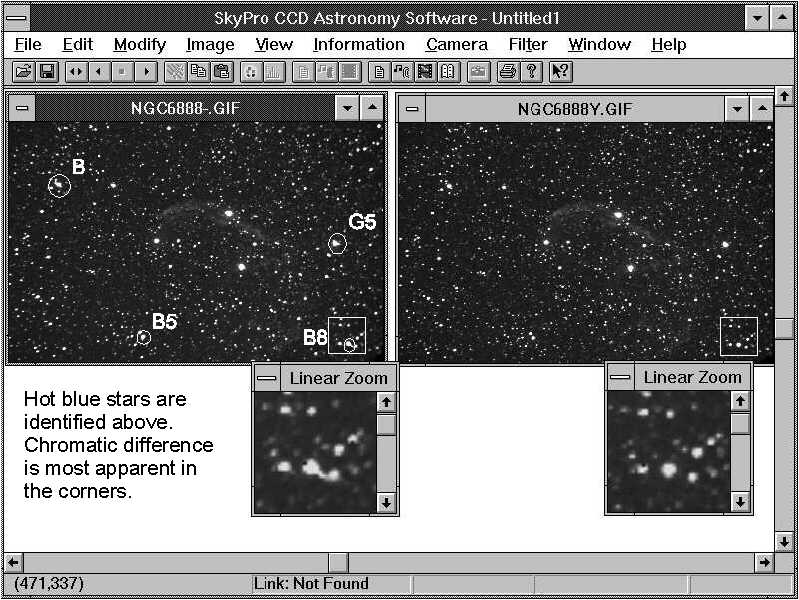
These images were all processed using SkyPro (now called CCDSoft) by Software Bisque. A SkyPro screen
shot is shown above comparing the two images above with a close up of the stars in the
lower right corner.
You've talked about "blur-spots".
What the heck is a blur spot anyway?
Blur spot analysis is a modeling technique
which uses optical ray tracing to determine the size and shape of the real image of an
infinitesimally small point of light after passing through a lens system. Blur spot
analysis allows an optical engineer to analyze a given optical system at a variety of
wavelengths. The blur spot images shown below were generated with the SCT/MAXfield optical
system.
Blur spots of the
MAXfield telecompressor system (left to right: On-axis, 70% field, edge-of-field.) Right
click with most viewers to see full resolution.
In these blur spot diagrams, blue represents blue light at 436nm, cyan
represents 480nm, green represents green light at 546nm, red represents red
light at 656nm, and magenta represents infrared light at about 852nm.
Click here to submit a new question.